Single and double diffusion breaks on integrated circuit products comprised of finfet devices

a technology of integrated circuit and finfet, which is applied in the direction of semiconductor devices, electrical devices, transistors, etc., can solve the problems of consuming very valuable plot space on the substrate b>12, difficult to form the desired isolation region made of an insulating material, and the design of the device spends a great amount of time and effort to maximiz

Active Publication Date: 2017-05-18
GLOBALFOUNDRIES US INC
View PDF21 Cites 58 Cited by
  • Summary
  • Abstract
  • Description
  • Claims
  • Application Information

AI Technical Summary

Problems solved by technology

Thus, device designers spend a great amount of time and effort to maximize device performance while seeking ways to reduce manufacturing costs and improve manufacturing reliability.
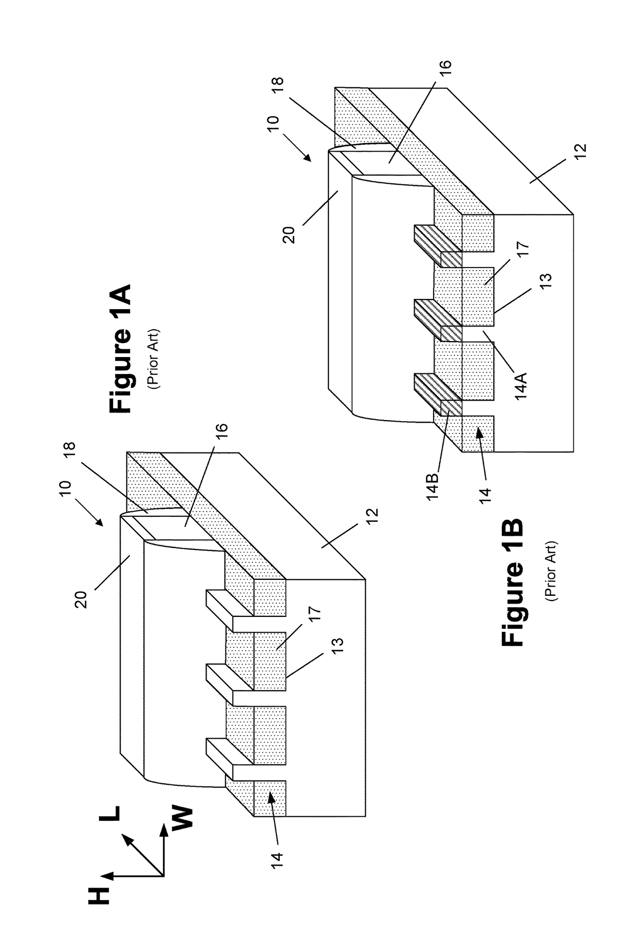
Within the industry, these isolation regions may sometimes be referred to as “diffusion breaks.” However, the formation of such isolation structures consumes very valuable plot space on the substrate 12.
Moreover, in some applications, such as those integrated circuit products employing FinFET transistor devices, as device sizes have decreased, and packing densities have increased, it is sometimes difficult to form the desired isolation region made of an insulating material.
Unfortunately, performing the fin cut process prior to formation of the gate structures can be detrimental as it relates to retaining desired stress conditions (e.g., compressive or tensile) when the fins are cut as there is no “anchoring structure” such as gate structures to source / drain epi material to help maintain or at least reduce the loss of some of the desired stress profiles created in the fins.
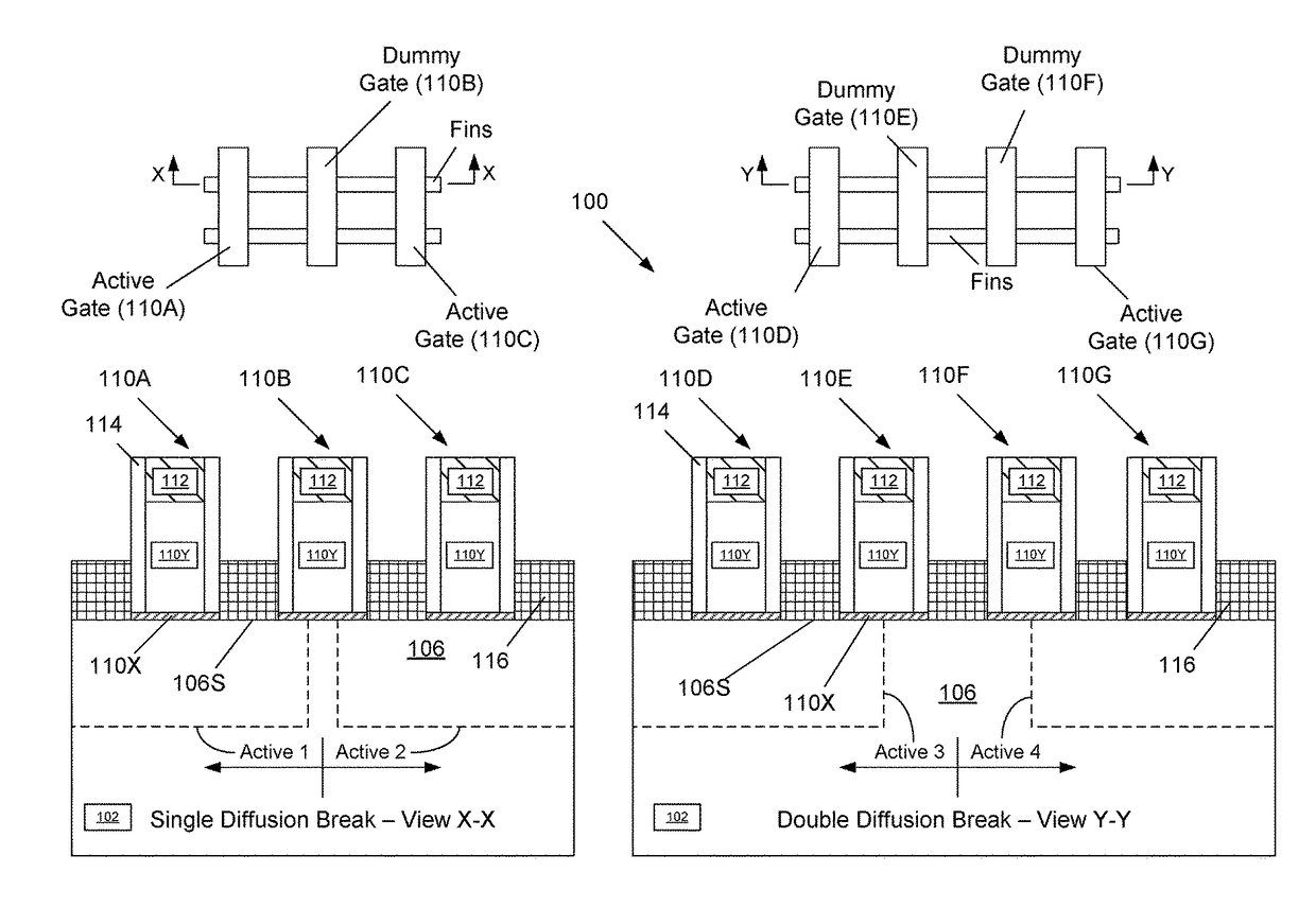
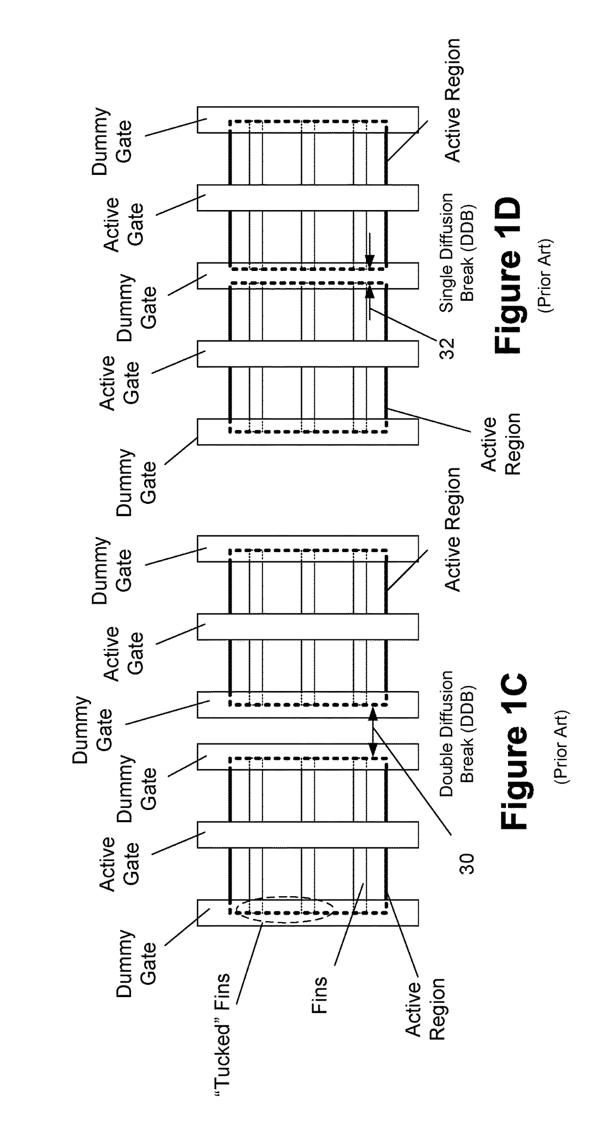
However, the use of such double diffusion break (DDB) isolation structures consumes more of the available plot space on a substrate than does the use of single diffusion break (SDB) isolation structures, thereby leading to reduced packing densities.
As noted above, one problem that can arise is loss of or reduction in desired stress profiles (compressive or tensile) that are intentionally created in fins when the fins are cut prior to forming any supporting structure, e.g., gates and / or source / drain epi material.
While cutting the fins after formation of the gate structures can be readily performed when forming double diffusion break (DDB) isolation structures, such a process will not work when forming single diffusion break (SDB) isolation structures because the portions of the fins to be removed are covered by a gate structure.
As an initial matter, it would be very challenging to properly align the opening 36 with the replacement gate cavity.
However, such an approach is more problematic when forming double diffusion break (DDB) isolation structures.
The presence of such residual fin material may lead to an undesirable increase in capacitance.
In cases where both double diffusion break (DDB) isolation structures and single diffusion break (SDB) isolation structures are formed, it would be possible to form both of such structures after formation of the gate structures, but it would involve formation of two separate cut masks—one mask for the DDB structures and another mask for the SDB structures—which would add to processing costs and complexity.

Method used


Image

  • Single and double diffusion breaks on integrated circuit products comprised of finfet devices
  • Single and double diffusion breaks on integrated circuit products comprised of finfet devices
  • Single and double diffusion breaks on integrated circuit products comprised of finfet devices

Examples


Embodiment Construction

[0024]Various illustrative embodiments of the invention are described below. In the interest of clarity, not all features of an actual implementation are described in this specification. It will of course be appreciated that in the development of any such actual embodiment, numerous implementation-specific decisions must be made to achieve the developers' specific goals, such as compliance with system-related and business-related constraints, which will vary from one implementation to another. Moreover, it will be appreciated that such a development effort might be complex and time-consuming, but would nevertheless be a routine undertaking for those of ordinary skill in the art having the benefit of this disclosure.

[0025]The present subject matter will now be described with reference to the attached figures. Various structures, systems and devices are schematically depicted in the drawings for purposes of explanation only and so as to not obscure the present disclosure with details ...


PUM


Abstract

One illustrative integrated circuit product disclosed herein includes, among other things, a plurality of FinFET devices, each of which comprises a gate structure comprising a high-k gate insulation material and at least one layer of metal, a single diffusion break (SDB) isolation structure positioned in a first trench defined in a semiconductor substrate between first and second active regions, the SDB isolation structure comprising the high-k insulating material and the at least one layer of metal, and a double diffusion break (DDB) isolation structure positioned in a second trench defined in a semiconductor substrate between third and fourth active regions, the DDB isolation structure comprising a first insulating material that substantially fills the second trench.

Description

BACKGROUND OF THE INVENTION[0001]1. Field of the Invention[0002]Generally, the present disclosure relates to the manufacture of semiconductor devices, and, more specifically, to various novel single and double diffusion break structures on integrated circuit (IC) products comprised of FinFET devices.[0003]2. Description of the Related Art[0004]In modern integrated circuits, such as microprocessors, storage devices and the like, a very large number of circuit elements, especially transistors, are provided on a restricted chip area. Transistors come in a variety of shapes and forms, e.g., planar transistors, FinFET transistors, nanowire devices, etc. The transistors are typically either NMOS (NFET) or PMOS (PFET) type devices wherein the “N” and “P” designation is based upon the type of dopants used to create the source / drain regions of the devices. So-called CMOS (Complementary Metal Oxide Semiconductor) technology or products refers to integrated circuit products that are manufactur...

Claims


Application Information

Patent Timeline
Patent Type & Authority Applications(United States)
IPC IPC(8): H01L29/66H01L27/088H01L29/06
CPCH01L29/66545H01L27/0886H01L29/0653H01L29/66795H01L29/7848H01L21/823431H01L21/845H01L29/785H01L27/1211H01L21/76224
Inventor XIE, RUILONGLIM, KWAN-YONGSUNG, MIN GYUKIM, RYAN RYOUNG-HAN
Owner GLOBALFOUNDRIES US INC
Why Eureka
Try Eureka