Eureka AIR delivers breakthrough ideas for toughest innovation challenges, trusted by R&D personnel around the world.

Pressurized Fluid-Submerged, Internal, Close-Range Photogrammetry System for Laboratory Testing

a technology of pressure-submerged fluid and photogrammetry system, which is applied in the direction of liquid/fluent solid measurement, television system, instruments, etc., can solve the problems of refraction of light through the lens, the optical elements of camera equipment have not been addressed in detail, and the cost of the camera surrounding the testing apparatus is high

Active Publication Date: 2017-05-25
THE BOARD OF TRUSTEES OF THE UNIV OF ARKANSAS
View PDF5 Cites 21 Cited by
  • Summary
  • Abstract
  • Description
  • Claims
  • Application Information

AI Technical Summary

Benefits of technology

The present invention provides a system that can remotely monitor a specimen during testing, capture digital images and videos, and create a three-dimensional model of the specimen using photogrammetry principles. The system also offers solutions for monitoring specimens during testing, designs high-quality cameras for confined spaces, and accurately measures important parameters such as specimen dimensions, cross-sectional area, level of strain, volume, and failure plane angle over time. These technical effects help in predicting the behavior of the specimen and facilitate constitutive modeling.

Problems solved by technology

Furthermore, the cameras surrounding the testing apparatus have been expensive and have required an excessive amount of space to develop the required focal length and lighting conditions.
Moreover, the optical elements of the camera equipment have not been addressed in detail, such as optical aberrations, inherent to the camera lenses.
However, errors introduced by refraction of light through lenses, including spherical aberration, coma, field curvature, astigmatism, and barrel, pincushion, and complex distortions are prevalent to varying extents in lenses.
A careful balance between mitigating one type of aberration and augmenting another type has always existed; therefore it is never truly possible to capture an image that does not contain some type of aberration when a lens or lens array is utilized.
The optimal pinhole diameter is limited by resolution (larger diameters correspond with poorer resolution), by Fresnel (near-field) and Fraunhofer (far-field) diffraction limits, and by the ability to gather light (smaller diameters correspond with higher diffraction interference and allow less light to be collected).
These housings are typically bulky, expensive, and do not allow for direct optical observation because light must first pass through a transparent thermoplastic barrier (i.e. acrylic plastic) before reaching the camera.

Method used


Image

  • Pressurized Fluid-Submerged, Internal, Close-Range Photogrammetry System for Laboratory Testing
  • Pressurized Fluid-Submerged, Internal, Close-Range Photogrammetry System for Laboratory Testing
  • Pressurized Fluid-Submerged, Internal, Close-Range Photogrammetry System for Laboratory Testing

Examples


Embodiment Construction

[0040]Detailed embodiments of the present invention are disclosed herein; however, it is to be understood that the disclosed embodiments are merely exemplary of the invention, which may be embodied in various forms. Therefore, specific structural and functional details disclosed herein are not to be interpreted as limiting, but merely as a representative basis for teaching one skilled in the art to variously employ the present invention in virtually any appropriately detailed method, structure or system. Further, the terms and phrases used herein are not intended to be limiting, but rather to provide an understandable description of the invention.

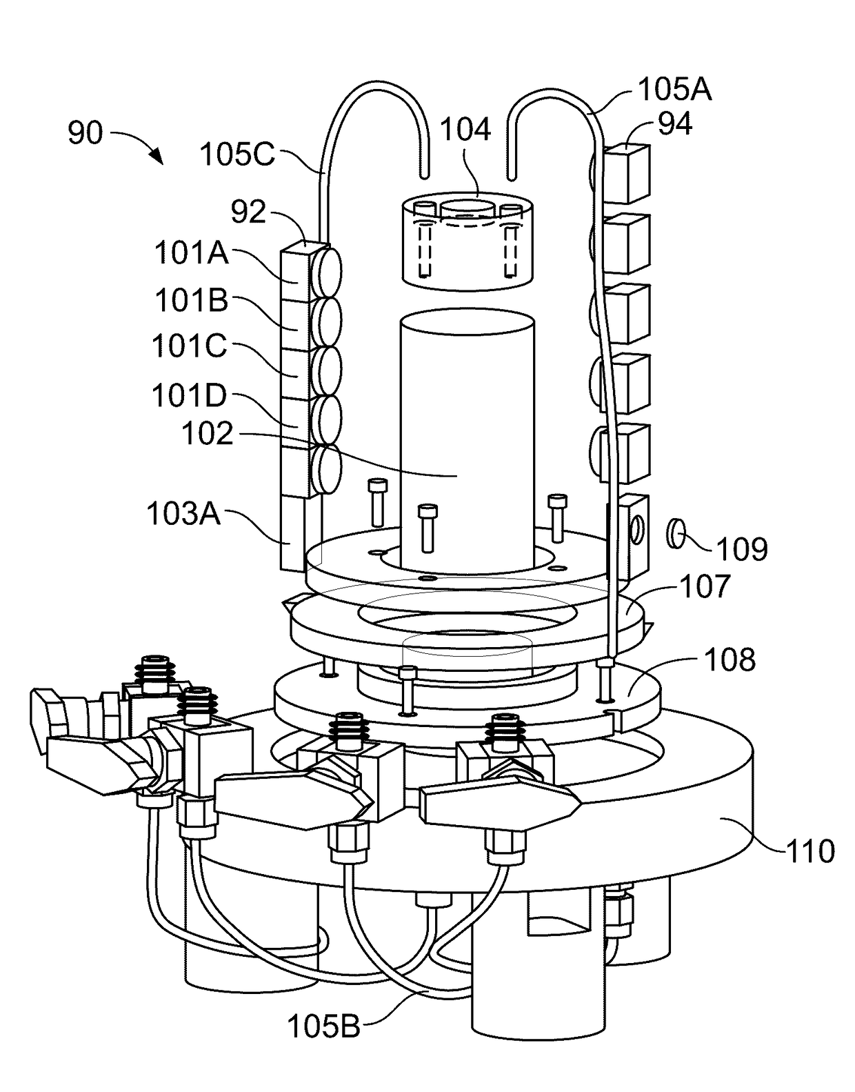
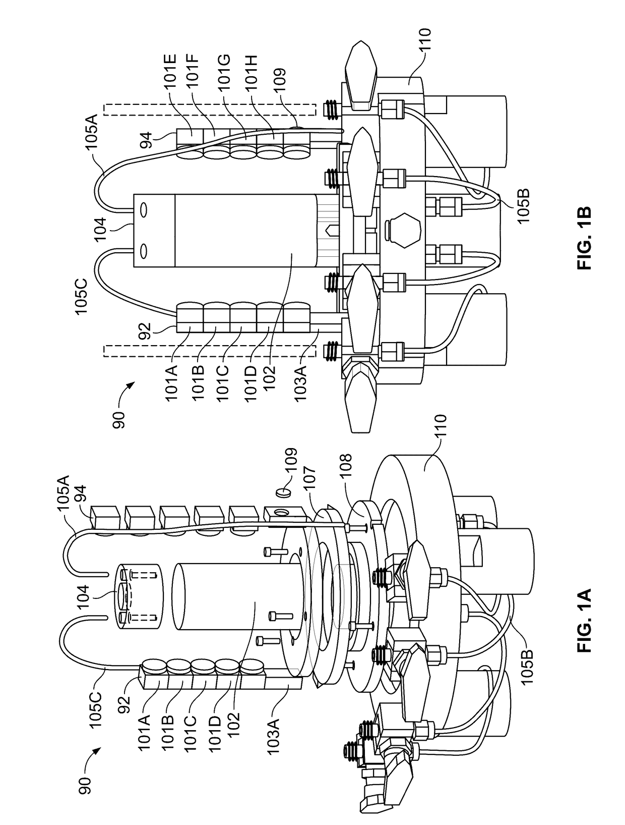
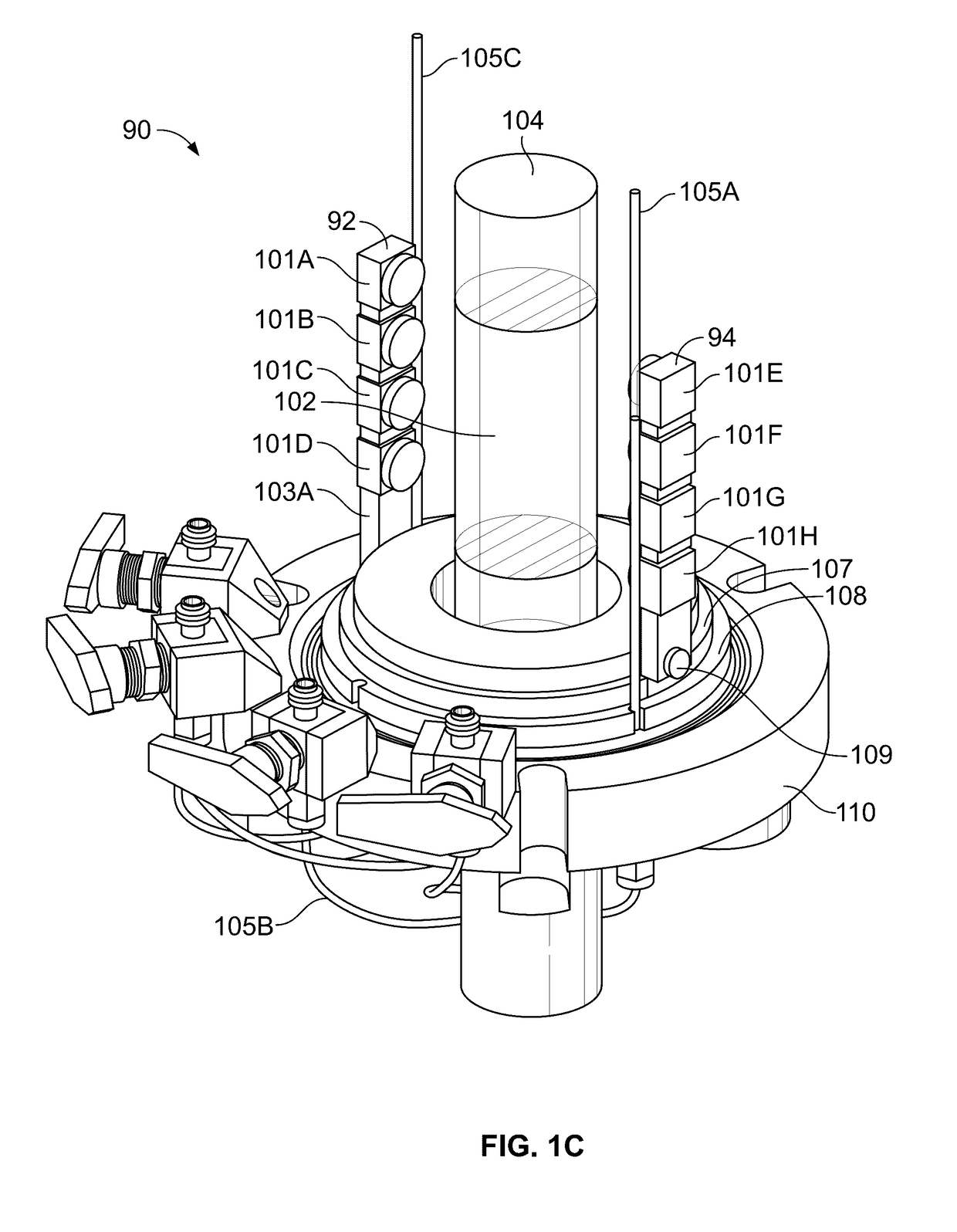
[0041]As shown in FIG. 1, in one embodiment, the present invention provides an imaging system 90 configured for analyzing a sample, such as a soil sample 102, that may be located in transparent container 104. Container 104 may include drain lines 105A-105C and is, in turn, located in a sealed container known as a triaxial cell (not shown).

[...


PUM


Abstract

A device for measuring strain and volume of a soil sample including an enclosure adapted to receive a soil sample within another enclosure. A base adapted to hold the sample enclosure. The device also has a plurality of moveable arms located between the enclosures which may be a spaced distance apart and adapted to move around the sample. Cameras as included on the arms.

Description

RELATED APPLICATIONS[0001]Not applicable.STATEMENT REGARDING FEDERALLY SPONSORED RESEARCH & DEVELOPMENT[0002]Not applicable.INCORPORATION BY REFERENCE OF MATERIAL SUBMITTED ON A COMPACT DISC[0003]Not applicable.BACKGROUND OF THE INVENTION[0004]Historically, when photogrammetric techniques were employed to measure the amount of volume change in specimens being tested in a triaxial device, outside-of-the-cell cameras were utilized. However, light refraction at the 1) confining fluid-cell wall interface and 2) cell wall-atmosphere interface and the curvature of the cell wall have necessitated the use of models to account for the refraction and magnification effects. Furthermore, the cameras surrounding the testing apparatus have been expensive and have required an excessive amount of space to develop the required focal length and lighting conditions. Moreover, the optical elements of the camera equipment have not been addressed in detail, such as optical aberrations, inherent to the ca...

Claims


Application Information

Patent Timeline
IPC IPC(8): H04N5/225G01N3/08G01N3/24G01F17/00G01N33/24
CPCH04N5/2252G01F17/00G01N33/24H04N2005/2255G01N3/08G03B19/16G01N3/24G01N3/068G01N3/12G01N2203/0069G01N2203/0256G01N2203/0284G01N2203/0647H04N23/51H04N23/698H04N23/90
Inventor SALAZAR, SEAN E.COFFMAN, RICHARD A.
Owner THE BOARD OF TRUSTEES OF THE UNIV OF ARKANSAS
Why Eureka
Eureka Blog
Learn More