Electrodynamic field strength triggering system

a technology of electrodynamic field and triggering system, which is applied in the field of electrodynamic field strength triggering system, can solve the problems of insufficient field strength range, inability to achieve the correct alignment, and difficulty in finding the correct alignment, so as to reduce the action required and achieve the effect of sufficient field strength rang

a technology of electrodynamic field and triggering system, which is applied in the field of electrodynamic field strength triggering system, can solve the problems of insufficient field strength range, inability to achieve the correct alignment, and difficulty in finding the correct alignment, so as to reduce the action required and achieve the effect of sufficient field strength rang

US20170150901A1Active Publication Date: 2017-06-01SENSEONICS INC

Image

  • Electrodynamic field strength triggering system
  • Electrodynamic field strength triggering system
  • Electrodynamic field strength triggering system

Examples


Embodiment Construction

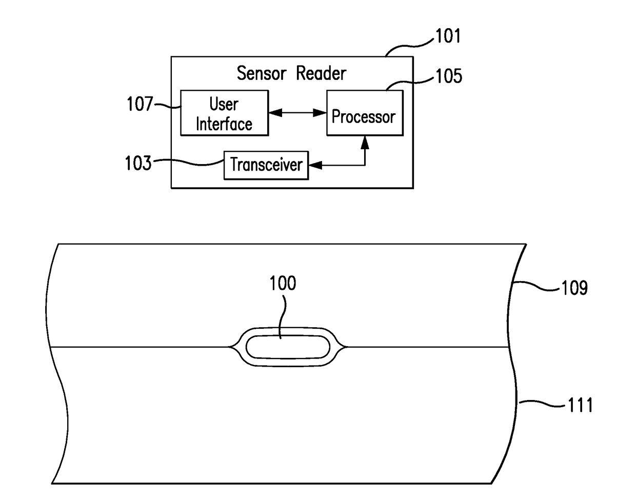
[0050]FIG. 1 is a schematic view of a sensor system embodying aspects of the present invention. In one non-limiting embodiment, the system includes a sensor 100 and an external sensor reader 101. In the embodiment shown in FIG. 1, the sensor 100 is implanted in a living animal (e.g., a living human). The sensor 100 may be implanted, for example, in a living animal's arm, wrist, leg, abdomen, or other region of the living animal suitable for sensor implantation. For example, as shown in FIG. 1, in one non-limiting embodiment, the sensor 100 may be implanted between the skin 109 and subcutaneous tissues 111. In some embodiments, the sensor 100 may be an optical sensor. In some embodiments, the sensor 100 may be a chemical or biochemical sensor.

[0051]A sensor reader 101 may be an electronic device that communicates with the sensor 100 to power the sensor 100 and / or obtain analyte (e.g., glucose) readings from the sensor 100 on demand. In non-limiting embodiments, the reader 101 may be ...


PUM


Abstract

Systems and methods for automatically triggering wireless power and data exchange between an external reader and an implanted sensor. The implanted sensor may measure the strength of an electrodynamic field received wirelessly from the reader and convey field strength data based on the measured strength of the received electrodynamic field to the reader. If the field strength data indicates that the strength of an electrodynamic field received by the sensor is sufficient for the implanted sensor to perform an analyte measurement, the reader may convey an analyte measurement command to the sensor, which may execute the analyte measurement command and convey measurement information back to the reader. The systems and methods may trigger the analyte measurement as the reader transiently passes within sufficient range / proximity to the implant (or vice versa).

Description

CROSS-REFERENCE TO RELATED APPLICATIONS[0001]This application is a continuation of U.S. patent application Ser. No. 13 / 650,016, filed on Oct. 11, 2012, which claims priority to U.S. Provisional Application No. 61 / 545,874, filed on Oct. 11, 2011, and U.S. Provisional Application No. 61 / 597,496, filed on Feb. 10, 2012, all of which are incorporated by reference herein in their entireties.BACKGROUND[0002]Field of the Invention[0003]The present invention relates to a system for obtaining analyte measurements. Specifically, the present invention relates to an external reader that can interrogate an implanted analyte sensor.[0004]Description of the Background[0005]In a system in which an external sensor reader provides power to an implanted sensor for operation (e.g., analyte measurement) and data transfer, the primary coil of the external sensor reader must be appropriately aligned with the secondary coil of the implanted sensor. However, there is a finite and relatively short range (typ...

Claims


Application Information

Patent Timeline
01 Jun 2017
Publication
US20170150901A1
IPC
A61B5/07; A61B5/145
CPC
A61B5/076; A61B2562/0257; A61B5/14503; A61B5/0031; A61B5/0022
Inventors
COLVIN, JR., ARTHUR E.; DEHENNIS, ANDREW