Architecture of an aircraft braking system

a technology of aircraft braking system and braking system, which is applied in the direction of braking system, aircraft braking arrangement, loop network, etc., can solve the problems of increasing the mass, complexity and cost of the computers, and achieve the effect of reducing the overall dimension, mass, complexity and cost of the braking system

Active Publication Date: 2017-06-01
SAFRAN LANDING SYSTEMS
View PDF0 Cites 12 Cited by
  • Summary
  • Abstract
  • Description
  • Claims
  • Application Information

AI Technical Summary

Benefits of technology

[0010]The invention aims at reducing the overall dimensions, mass, complexity and cost of a braking system.

Problems solved by technology

The extensive length of the cable assemblies wherein the supply wires 16 and thus the currents supplying the electric motors 10 run makes it necessary to use common mode current filtering circuits which increase the mass, complexity and cost of the computers 3.

Method used


Image

  • Architecture of an aircraft braking system
  • Architecture of an aircraft braking system
  • Architecture of an aircraft braking system

Examples


first embodiment

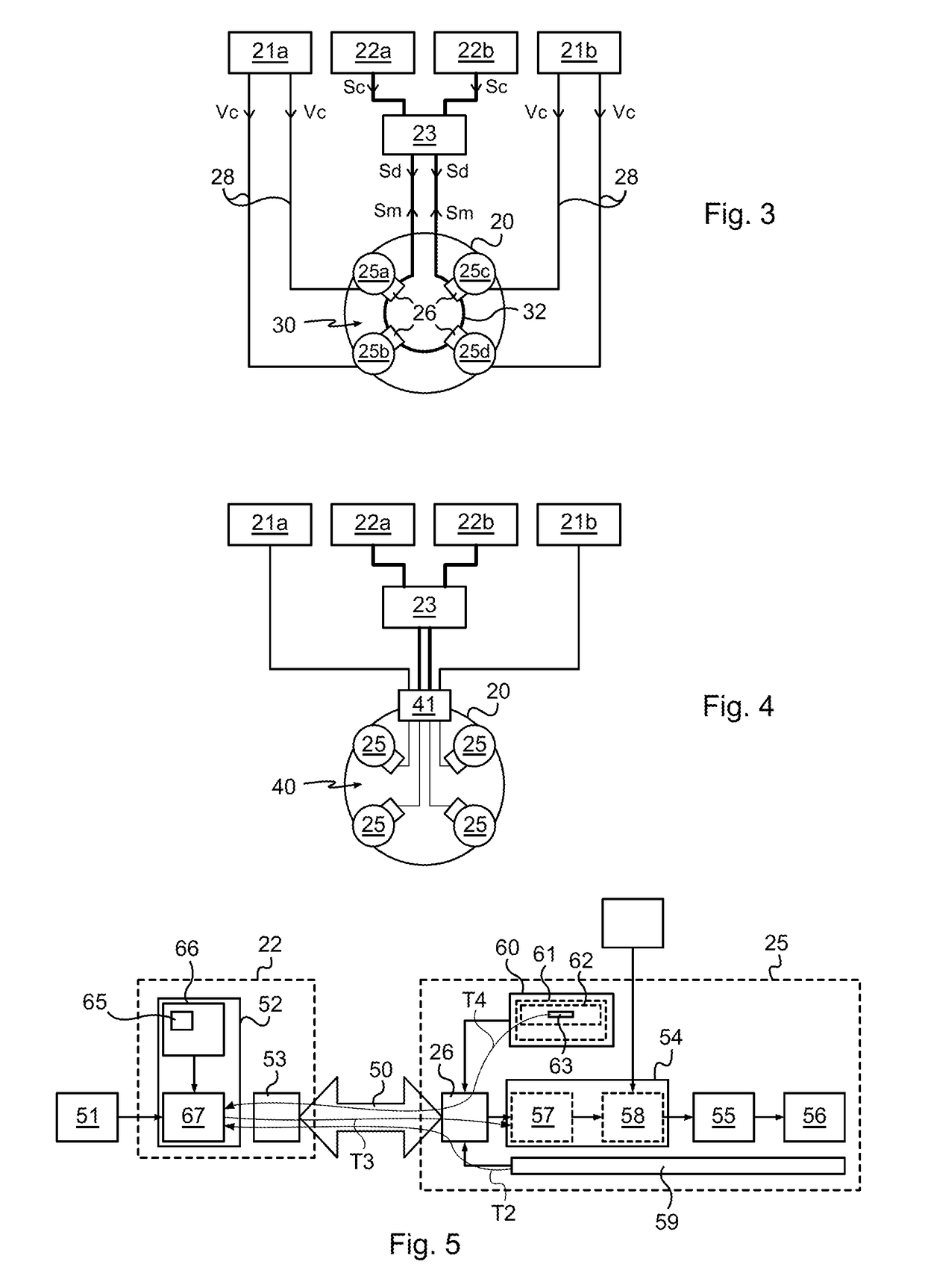
[0029]In reference to FIG. 3, a braking system architecture according to the invention thus comprises a brake 20 intended to brake a wheel of the aircraft, a first supply unit 21a, a second supply unit 21b, a first control unit 22a, a second control unit 22b and a network switch 23. It should be noted here that it would be possible to use a different network interconnection member, such as a router or a concentrator (or >), instead of a network switch, as well.

[0030]The brake 20 comprises an actuator-holder whereon four braking electromechanical actuators 25a, 25b, 25c, 25d and friction members, i.e. a stack of carbon disks are mounted.

[0031]The four electromechanical actuators 25 are used to apply a braking force onto the stack of carbon disks and thus exert a braking torque onto the wheel which slows down the rotation of the wheel and thus slows the aircraft down when the latter touches the ground.

[0032]Each electromechanical actuator 25 comprises a body attached to the actuator-h...

second embodiment

[0066]In the braking system architecture according to the invention, shown in FIG. 4, the digital network, this time, is a star digital network 40.

[0067]The network switch 23 forms a node of the digital star network 40 which all the electromechanical actuators 25 of the brake 20 are connected to.

[0068]It should be noted that the braking system architecture according to the second embodiment of the invention comprises, in addition to the four electromechanical actuators 25, the two power supply units 21, the two control units 22 and the network switch 23, a connexion box 41 mounted on the brake actuator-holders 20.

[0069]The four electromechanical actuators 25, the two power supply units 21, the two control units 22 and the network switch 23 are connected to the connexion box 41.

[0070]The connexion box 41 receives the continuous supply voltage and the downlink digital signals mentioned above, and distributes same to the electromechanical actuators 25 and to the tachometer and to the b...

third embodiment

[0097]Referring to FIG. 7, the actuating system according to the invention again comprises the control unit 22, the electromechanical actuator 25 and the digital transmission channel 50.

[0098]The non-volatile memory 60 of the electromechanical actuator 25 of the actuating system according to the third embodiment of the invention is also used for storing an identifier 80 of a servo-control algorithm to be used for the electromechanical actuator 25.

[0099]The configuration data 62 of the stored data 61 stored in the non-volatile memory 60 comprises an identifier 80 which enables the processing means 52 of the control unit 22 to select the servo-control algorithm to be used among a list of servo-control algorithms stored in the memory 66 of the processing means 52.

[0100]The list of servo-control algorithms comprises a servo-control algorithm 81 for an electromechanical actuator with an alternating current motor, a servo-control algorithm 82 for an electromechanical actuator with a direc...


PUM


Abstract

Architecture of an aircraft braking system comprising:
    • a brake (20) comprising a plurality of electromechanical actuators (25), with each electromechanical actuator (25) comprising a power module and a digital communication module (26), with the brake digital communication modules being interconnected to form a digital network (30);
    • two control units (22a, 22b) adapted for generating digital signals for controlling electric motors;
    • one network interconnection member (23) connected to two control units and incorporated in the digital network for distributing the digital control signals to the digital communication modules via the digital network.

Description

BACKGROUND OF THE INVENTION[0001]Many systems are provided aboard aircrafts, which consist of mobile parts which have to move.[0002]Wing elements (for example an aileron, a flap, an air brake), elements of the landing gear (for example a landing gear strut movable between an extended position and a retracted position, or a plunger of a brake of a wheel which slides relative to brake friction members), elements making it possible to implement variable geometry turbines, elements of a pump or a fuel metering mechanism, elements of the thrust reversers, elements of a propeller pitch driving mechanism (for example on an helicopter or a turboprop engine), etc. belong to such mobile parts.[0003]On modern aircrafts, more and more electromechanical actuators are used to implement such mobile parts. As a matter of fact, the advantages of using electromechanical actuators are numerous: simple electric distribution and driving, flexibility, simplified maintenance operations, etc.[0004]An elect...

Claims


Application Information

Patent Timeline
Patent Type & Authority Applications(United States)
IPC IPC(8): B64C25/44F16D65/18H04L29/08H04L12/42H04L12/44
CPCB64C25/44H04L12/42F16D2121/24H04L67/12F16D65/18H04L12/44B60T13/741B64C25/42F16D55/226F16D65/183
Inventor ONFROY, DOMINIQUEGOYEZ, BRIANCOUSTENOBLE, STEVEEVENOR, ERIC
Owner SAFRAN LANDING SYSTEMS
Why Eureka
Try Eureka