Wind-turbine rotor blade, trailing edge for wind-turbine rotor blade tip, method for producing a wind-turbine rotor blade, and wind turbine

a technology of wind turbines and rotor blades, which is applied in the direction of wind turbines, motors with parallel air flow, wind turbines, etc., can solve the problems of disproportionate effort in relation to the effect, difficult design to achieve the desired reduction in noise or power output, and noise produced, so as to increase the effectiveness of rotor blades and increase noise effects.

Active Publication Date: 2017-06-01
WOBBEN PROPERTIES GMBH
View PDF2 Cites 3 Cited by
  • Summary
  • Abstract
  • Description
  • Claims
  • Application Information

AI Technical Summary

Benefits of technology

[0007]One or more embodiments are directed to a solution that increases the effe...

Problems solved by technology

When a flow passes around the rotor blade tip, a difference in pressure between the upper side and the underside causes free edge turbulences, resulting in a resistance.
Moreover, disturbing noises are produced by these free edge tu...

Method used


Image

  • Wind-turbine rotor blade, trailing edge for wind-turbine rotor blade tip, method for producing a wind-turbine rotor blade, and wind turbine
  • Wind-turbine rotor blade, trailing edge for wind-turbine rotor blade tip, method for producing a wind-turbine rotor blade, and wind turbine
  • Wind-turbine rotor blade, trailing edge for wind-turbine rotor blade tip, method for producing a wind-turbine rotor blade, and wind turbine

Examples


Embodiment Construction

[0050]It should be noted that the same designations may possibly denote elements that are similar but not identical and may also be of different embodiments.

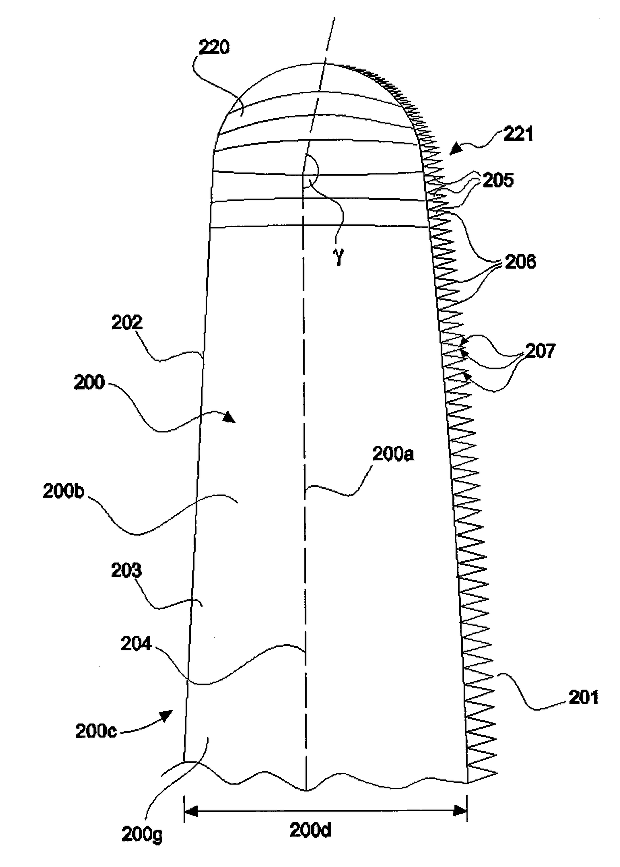
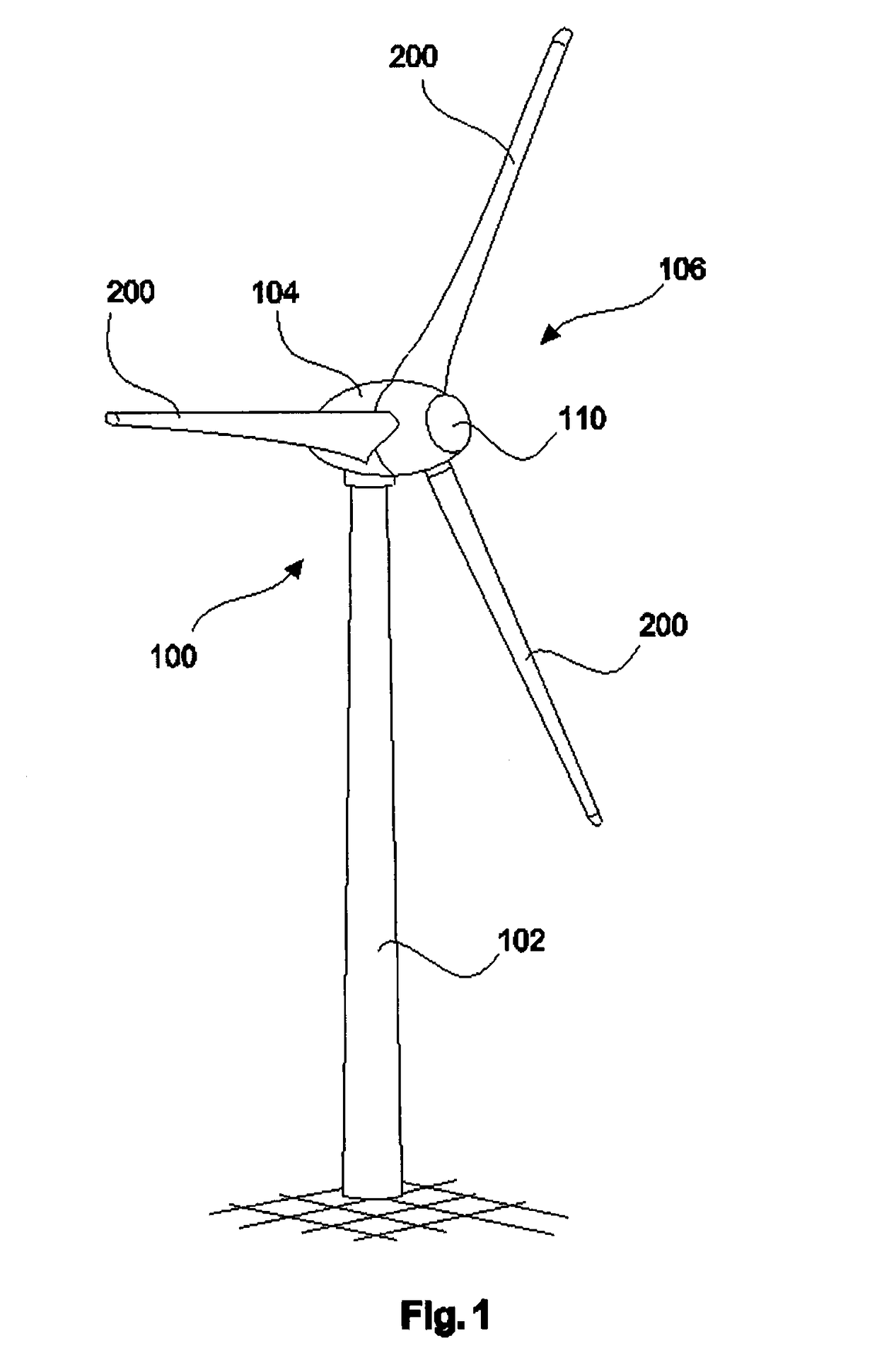
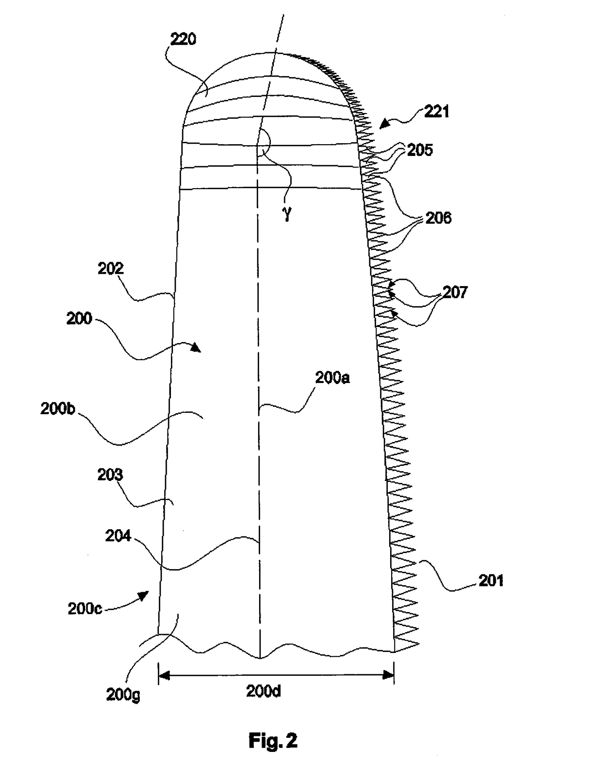
[0051]The explanation of the invention on the basis of examples with reference to the figures is substantially schematic, and, for the sake of better illustration, the elements that are explained in the respective figure may be exaggerated in it and other elements simplified. Thus, for example, FIG. 1 schematically illustrates a wind turbine as such, and so the intended serrated trailing edge on the rotor blade tip and the winglet form of the rotor blade tip cannot be clearly seen.

[0052]FIG. 1 shows a wind turbine 100 with a tower 102 and a nacelle 104. Arranged on the nacelle 104 is a rotor 106 with three rotor blades 200 and a spinner 110. During operation, the rotor 106 is set in a rotational movement by the wind and thereby drives a generator in the nacelle 104. The pitch of the rotor blade can be set for example in each cas...


PUM


Abstract

A trailing edge for a rotor blade tip of an aerodynamic rotor of a wind turbine. The trailing edge comprises a trailing edge delimiting line, which replicates the contour of the trailing edge, and multiple serrations to improve flow behavior at the trailing edge. The serrations are provided at the trailing edge in dependence on the trailing edge delimiting line, and consequently on geometrical and operating parameters.

Description

BACKGROUND[0001]Technical Field[0002]The invention relates to a method for producing a wind turbine rotor blade. The invention also relates to a trailing edge for a rotor blade tip and the invention relates to a wind turbine rotor blade.[0003]Description of the Related Art[0004]Wind turbines are generally known and FIG. 1 shows such a known wind turbine. The design of the rotor blade or rotor blades is an important aspect for the efficiency of the wind turbine. The form of the rotor blade tip is also an important factor here. When a flow passes around the rotor blade tip, a difference in pressure between the upper side and the underside causes free edge turbulences, resulting in a resistance. Moreover, disturbing noises are produced by these free edge turbulences.[0005]To reduce these disturbing noises, so-called winglets are already known. A winglet should be understood as meaning an attachment to the ends of a rotor blade that deviates from the longitudinal axis of the rotor blade...

Claims


Application Information

Patent Timeline
IPC IPC(8): F03D1/06
CPCF05B2260/96F03D1/0633F03D1/0675Y02E10/72
Inventor KAMRUZZAMAN, MOHAMMADALTMIKUS, ANDREE
Owner WOBBEN PROPERTIES GMBH
Why Eureka
Try Eureka