
Network system for positioning services based on wireless communication technologies

Active Publication Date: 2017-06-01
LEGAO LEJIA BEIJING INFORMATION TECH CO LTD
View PDF7 Cites 6 Cited by
  • Summary
  • Abstract
  • Description
  • Claims
  • Application Information

AI Technical Summary

Benefits of technology

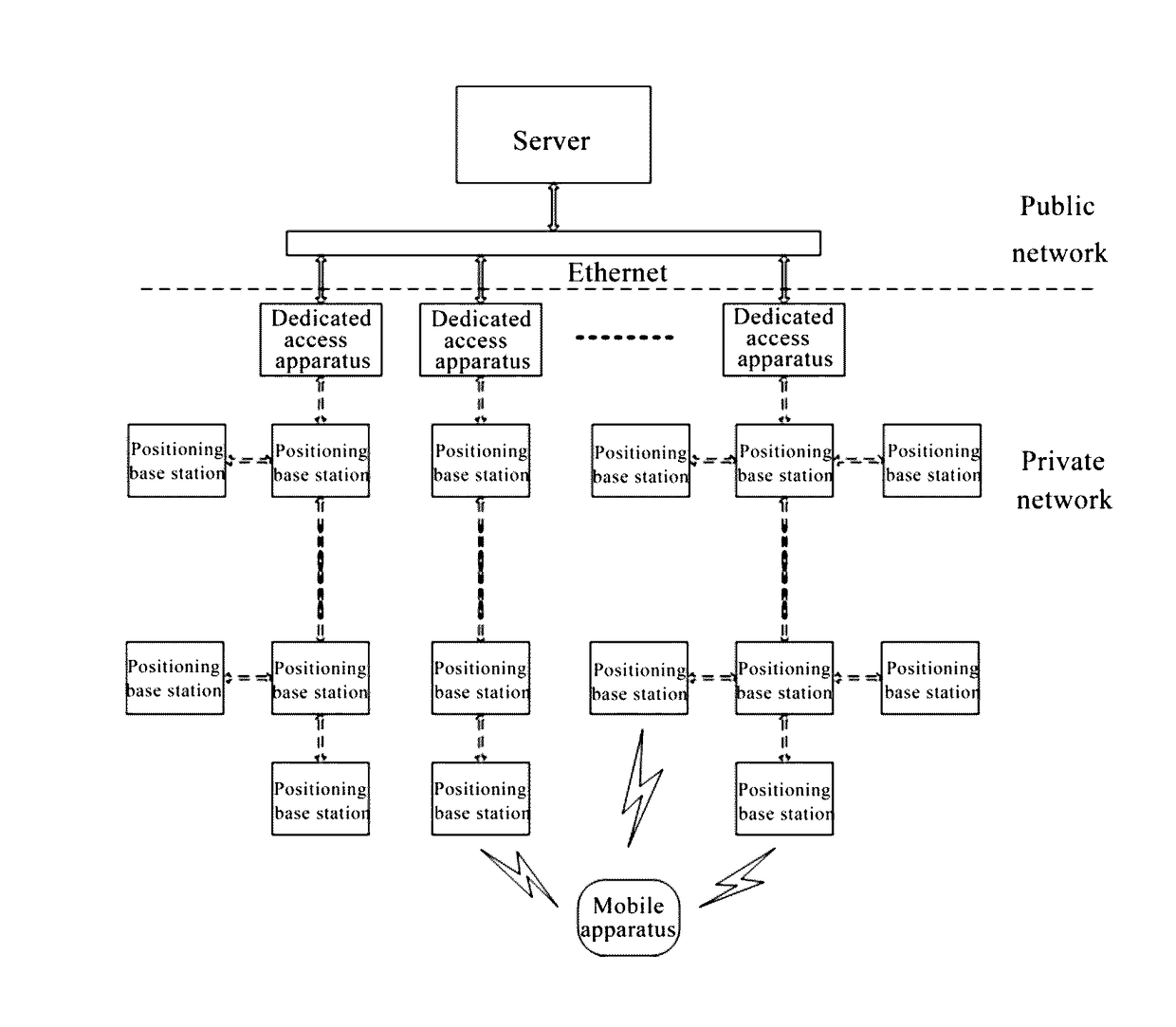
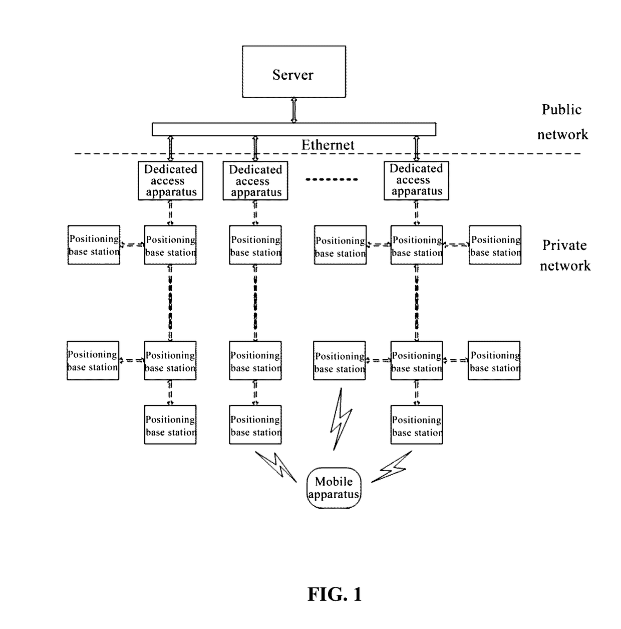
The present invention provides a network system for positioning services that can realize effective, reliable and accurate indoor positioning. The network system is designed to offer efficient and low-maintenance electricity supply and a flexible tree network structure that is easy to extend. Additionally, the network system allows for real-time communication and mutual monitoring between base stations, avoiding detection by operators on site and realizing self-monitoring.

Problems solved by technology

However, when a user is indoors, the positioning function of these systems can hardly be realized.
However, with the continuous development of cities, large modern buildings (shopping malls, large hospitals and exhibition centers) develop faster and become larger in size.
One way is based on the wireless communication technologies including Wi-Fi, Bluetooth, ZigBee or more, wherein the Wi-Fi-based positioning can only achieve meter-level positioning and has very poor positioning accuracy; for the Bluetooth-based positioning, the signal intensity will be weakened with the drop in the battery voltage which means the positioning accuracy is instable, and due to the dot-like dispersed installation and arrangement mode, it is unable to form a uniform network so that it is difficult to conduct subsequent management; and for the ZigBee positioning, it is required to deploy a dedicated sensor network so that the implementation cost is high and it is disadvantageous for popularization.
Therefore, how to effectively and reliably construct an indoor positioning network and an indoor positioning system to realize indoor positioning with high accuracy and high efficiency is a problem to be solved.

Method used


Image

  • Network system for positioning services based on wireless communication technologies
  • Network system for positioning services based on wireless communication technologies

Examples


Embodiment Construction

[0035]Embodiments of the present invention will be described in detail hereinafter. The examples of these embodiments have been illustrated in the drawings throughout which same or similar reference numerals refer to same or similar elements or elements having same or similar functions. The embodiments described with reference to the drawings are illustrative, merely used for explaining the present invention and should not be regarded as any limitations thereto.

[0036]It should be understood by a person skilled in this art that singular forms “a”, “an”, “the”, and “said” can be intended to include plural forms as well, unless otherwise stated. It should be further understood that terms “include / including” used in this specification specify the presence of the stated features, integers, steps, operations, elements and / or components, but not exclusive of the presence or addition of one or more other features, integers, steps, operations, elements, components, and / or combinations thereo...


PUM


Abstract

A network system for positioning services based on wireless communication system, including base stations, a dedicated access apparatus, cables, and a server. The base stations, the dedicated access apparatus and the cables constituting a private network. The server constituting a public network. The base stations are configured to send and receive signals in a broadcasting manner, and transmit the signals to the server through the cables and the dedicated access apparatus. The dedicated access apparatus is configured to transfer transmission data between the private network and the public network, forward data from the base stations to the server, and forward data from the server to a corresponding base station. The cables are configured to transmit data between the base stations and between the base stations and the dedicated access apparatus. The server is configured to perform data processing according to the received data collected by at least one base station.

Description

FIELD OF THE DISCLOSURE[0001]The present invention relates to network technologies. In particular to a network system for positioning services which are based on wireless communication technologies.BACKGROUND OF THE DISCLOSURE[0002]Currently, outdoor positioning is basically, recognized by a satellite-based positioning technology, such as GPS in America, GLONASS in Russia, BEIDOU in China and GALILEO in Europe. However, when a user is indoors, the positioning function of these systems can hardly be realized. However, with the continuous development of cities, large modern buildings (shopping malls, large hospitals and exhibition centers) develop faster and become larger in size. Consequently, the demands for indoor positioning and location-based services are growing. Therefore, indoor positioning becomes a goal to be solved urgently. One way is based on the wireless communication technologies including Wi-Fi, Bluetooth, ZigBee or more, wherein the Wi-Fi-based positioning can only ac...

Claims


Application Information

Patent Timeline
IPC IPC(8): H04W4/02H04L12/10H04L12/24G01S5/02H04W72/00H04L29/08H04B17/318H04B3/54H04W52/32H04W4/029
CPCH04W4/02H04B3/54H04L12/10H04L41/12H04L41/0672G01S5/021H04W72/005H04L67/34H04B17/318G01S5/0252H04W52/322H04W4/06H04W24/08H04W64/00H04W84/22G01S5/02521H04B17/309H04L41/0661H04W4/029
Inventor HAOYANG, YUANXIAN, WUJI, QI
Owner LEGAO LEJIA BEIJING INFORMATION TECH CO LTD
Learn More