Granulated body manufacturing apparatus and method

a technology of granulated bodies and manufacturing apparatus, which is applied in the direction of material granulation, transportation and packaging, coatings, etc., can solve the problems of increasing bulk density, affecting the crushing effect of granulated bodies, and insufficient particle diameter control, etc., to achieve small particle diameter and low bulk density

Active Publication Date: 2017-06-08
TOYOTA JIDOSHA KK
View PDF0 Cites 1 Cited by
  • Summary
  • Abstract
  • Description
  • Claims
  • Application Information

AI Technical Summary

Benefits of technology

[0007]However, the aforementioned technique has the following problems. If moist powder is used as a raw material for coating for forming a thin layer, it is preferable that the moist powder have a small particle diameter and a low bulk density. However, in the technique in JP 10-216575 A, particle diameter control is possible to a certain extent but...

Problems solved by technology

However, the aforementioned technique has the following problems.
However, in the technique in JP 10-216575 A, particle diameter control is possible to a certain extent but insuffici...

Method used


Image

  • Granulated body manufacturing apparatus and method
  • Granulated body manufacturing apparatus and method
  • Granulated body manufacturing apparatus and method

Examples


first embodiment

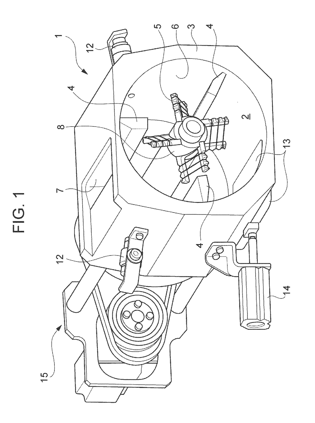
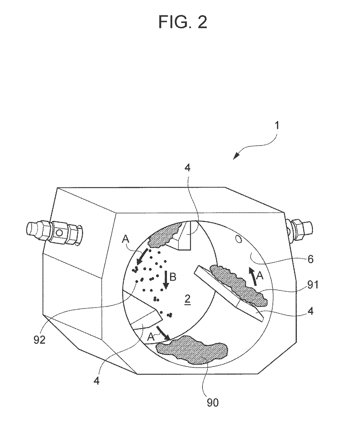
[0032]the disclosure will be described in detail below with reference to the attached drawings. The present embodiment is one in which the first aspect of the disclosure has been applied to a granulated body manufacturing apparatus 1 illustrated in FIG. 1 and a granulated body manufacturing method using the same. The manufacturing apparatus 1 in FIG. 1 includes a housing 3 including a cylindrical internal space 2 formed inside. The housing 3 is disposed so that a center axis direction of the internal space 2 is horizontal. In the housing 3, an inlet 7 for putting powder into the internal space 2 is provided. The inlet 7 is provided in an upper portion of the housing 3.

[0033]Inside the internal space 2 of the housing 3, agitation blades 4 and crossing blades 5 are provided. The agitation blades 4 and the crossing blades 5 both rotate around the center axis of the internal space 2. However, while the agitation blades 4 are provided so as to, upon being rotated, move along a cylindrica...

second embodiment

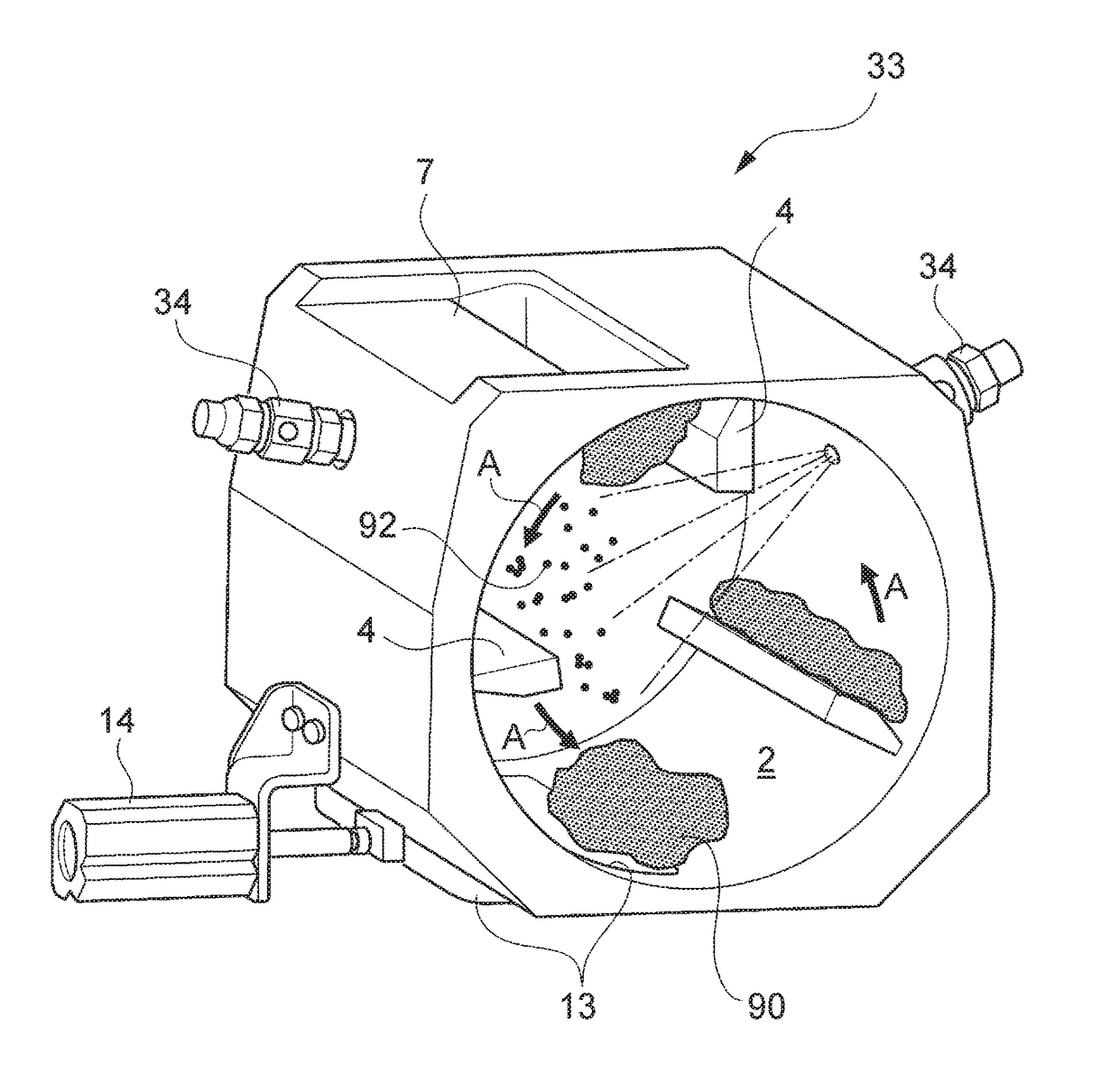
[0053]Next, a second embodiment will be described. In the present embodiment, a granulated body is manufactured in such a manner as illustrated in FIG. 13. A manufacturing apparatus 33 in FIG. 13 is similar to the manufacturing apparatus 1 in FIG. 1, but is different from the manufacturing apparatus 1 in the following point. In other words, a foaming nozzle 34 is provided instead of the injection nozzle 12. The foaming nozzle 34 is a nozzle that brings air into a liquid component to foam the liquid component and injects the foamed liquid component.

[0054]In the present embodiment, the crossing blades 5 in the manufacturing apparatus 1 in FIG. 1 may or may not be provided. FIG. 13 indicates an example of the case where no crossing blades 5 are provided. The below description will be provided on the premise that no crossing blades 5 are provided. In the manufacturing apparatus 33 in FIG. 13, agitation blades 4 are only rotary objects inside the internal space 2. The agitation blades 4 ...


PUM

PropertyMeasurementUnit
Lengthaaaaaaaaaa
Forceaaaaaaaaaa
Speedaaaaaaaaaa

Abstract

A granulated body manufacturing apparatus includes: a housing that includes a cylindrical internal space, is disposed so that a center axis direction of the internal space is horizontal, and houses a raw material for a granulated body inside the internal space; an agitation blade that is provided along an inner circumferential surface of the internal space, and upon being rotated around the center axis, scoops up the raw material accumulated in a bottom portion of the internal space and makes the raw material fall down from an upper position inside the internal space; and a crossing blade including a wire having a wire diameter not exceeding 0.3 mm, the wire being provided at a position in a range, inside the internal space, in which the crossing blade does not come into contact with the agitation blade, and being looped around a framework body that rotates around the center axis.

Description

INCORPORATION BY REFERENCE[0001]The disclosure of Japanese Patent Application No. 2015-237161 filed on Dec. 4, 2015 including the specification, drawings and abstract is incorporated herein by reference in its entirety.BACKGROUND[0002]1. Technical Field[0003]The disclosure relates to an apparatus and method for manufacturing a granulated body having a relatively-small liquid component content such as moist powder.[0004]2. Description of Related Art[0005]For forming a thin layer on a solid body, a coating process is used. In the coating process, a solid body is coated with a fluid substance (paste or slurry) obtained by kneading powder, which is a raw material for the thin layer, with a liquid. Subsequently, a drying process is performed to remove the liquid, whereby a layer of an aggregate of the powder is formed on the solid body. The processes such as above are used in, for example, manufacture of an electrode plate for a secondary battery.[0006]Because of large burden in the dryi...

Claims


Application Information

Patent Timeline
IPC IPC(8): B05D3/12B05D1/26B01F29/64
CPCB05D1/26B05D3/12B01J2/10B01J2/00B01F29/64
Inventor OZAKI, TAKEYUKISAKASHITA, YASUHIROIKEDA, TAKENORI
Owner TOYOTA JIDOSHA KK
Why Eureka
Try Eureka