
Reflective encoder

a technology of reflective encoder and encoder, which is applied in the direction of optical conversion of sensor output, instruments, measurement devices, etc., can solve the problems of reducing the freedom of design, reducing the accuracy of measurement, and reducing so as to simplify the structure of the existing reflective encoder and reduce the reliability of the encoder. , the effect of simplifying the structur

Inactive Publication Date: 2017-06-08
NAMIKI PRECISION JEWEL CO LTD +2
View PDF1 Cites 0 Cited by
  • Summary
  • Abstract
  • Description
  • Claims
  • Application Information

AI Technical Summary

Benefits of technology

The present patent describes a new reflective encoder that can measure movement and detect direction using one light beam. This is achieved by using an interference optical system between a light receiving element and a diffraction grating, which causes a phase difference between two diffracted light beams reflected by the grating. By enabling the two beams to interfere with each other, the encoder can measure movement and detect direction. The structure of the reflective encoder is simplified, leading to miniaturization and higher reliability, and the incident light is vertically incident on the diffraction grating, improving reliability. A small number of elements can be used to achieve accurate interference between the diffracted light beams and the emergent light.

Problems solved by technology

The existing technologies disclosed by the above two patent documents have their own technical features and technical effects, but neither of them can measure the movement amount and detect the movement direction by using only one light beam.
Therefore, when a rotary encoder adopts the above structure, it, due to a circumferential difference between the inner channel and the outer channel, will have the problem that an upper value of resolution thereof will be determined by the relatively narrow pitch (i.e., center-to-center distance between two adjacent slits) of the inner channel, rather than by the relatively wide pitch of the outer channel.
This may lead to problems that a pitch of the reflective diffraction grating as the scale will be determined by a corresponding pitch of the reflection angle, and a distance between the detecting elements and the diffraction grating on the moving portion will also be determined by the reflection angle defined, thus reducing the freedom to design.
Because the interference for detecting the movement of the diffraction grating based on the change of the distance between the detecting elements and the diffraction grating on the moving portion also changes, the encoder in practical use will fail to adapt to the change of said distance, whereby the accuracy of the measurement will be decreased.
Moreover, the implementation of the above existing reflective encoders is based on a complex wiring system and a three-dimensional configuration, which requires sophisticated techniques, and cannot meet the requirement for miniaturization of components such manipulator.

Method used


Image

  • Reflective encoder
  • Reflective encoder
  • Reflective encoder

Examples


Embodiment Construction

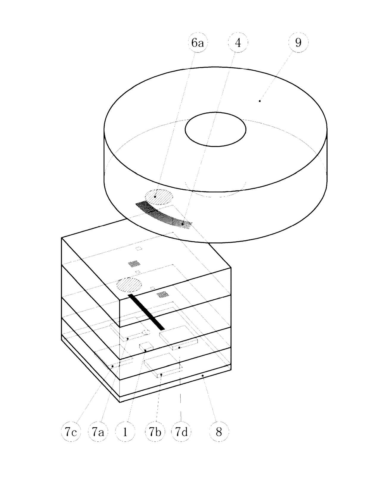
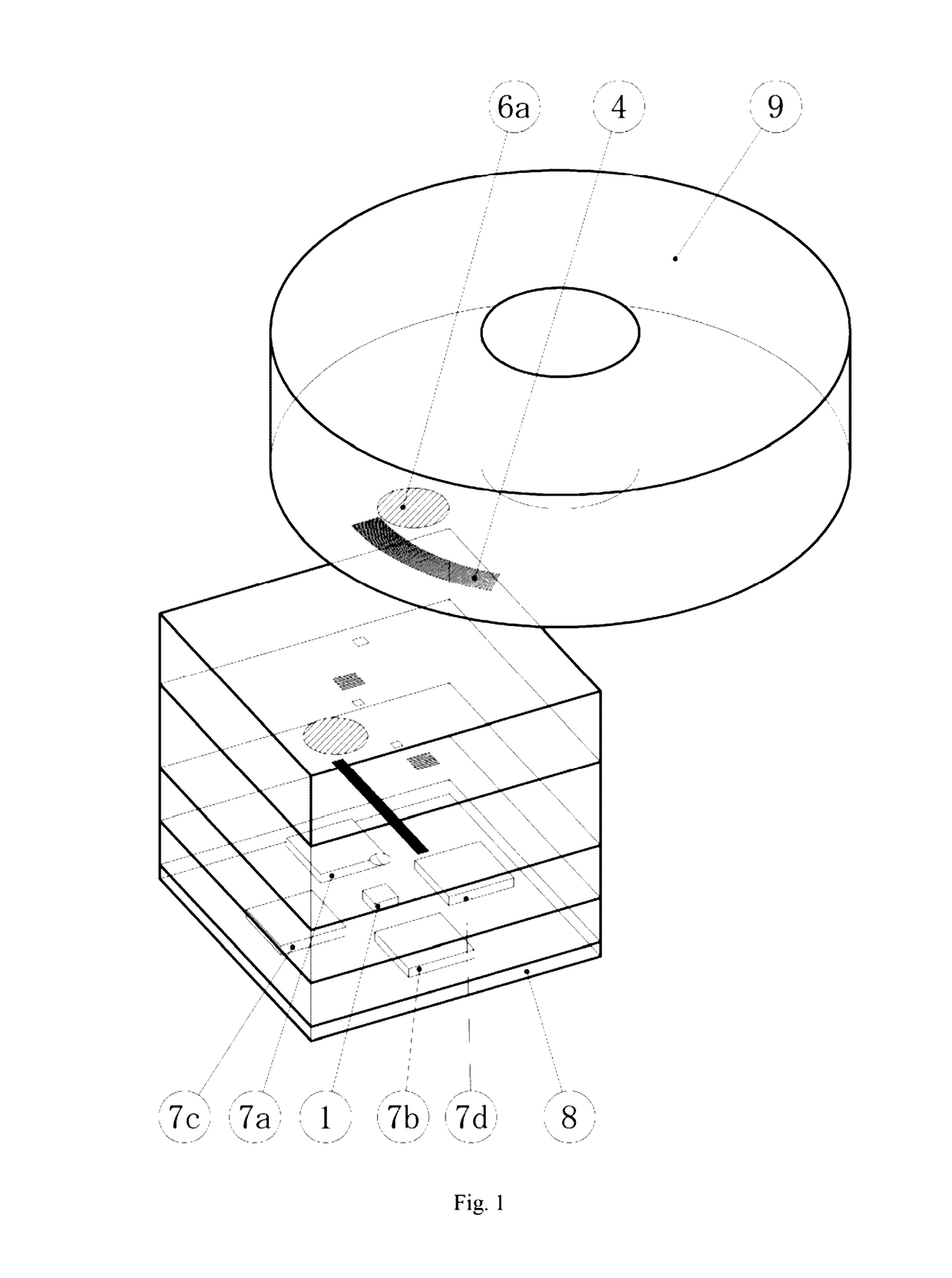
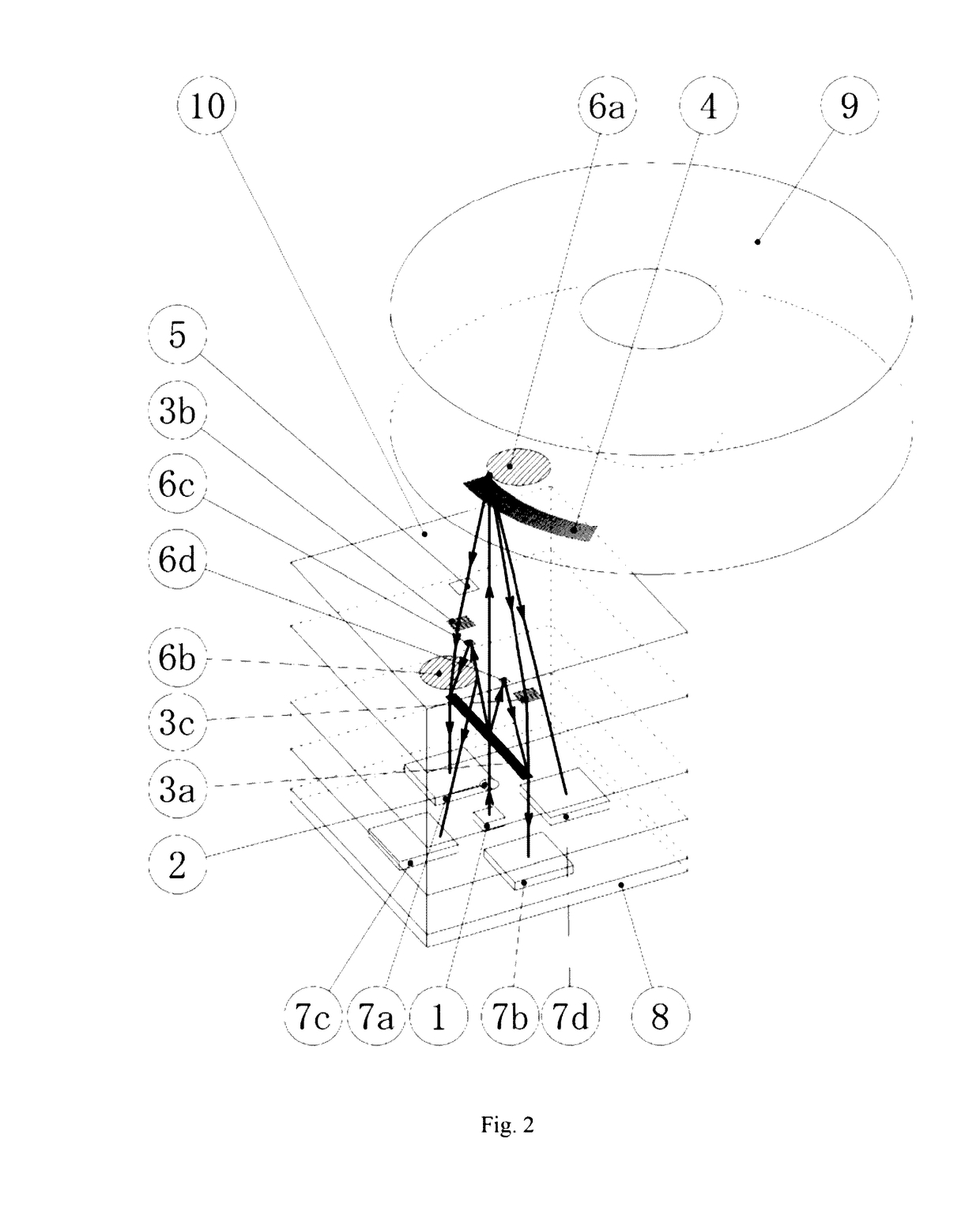
[0022]Preferable embodiments of the present disclosure are described in the following with reference to FIGS. 1 to 6, in which same elements are indicated with a same reference sign.

[0023]FIG. 1 shows a perspective view of a reflective encoder according to the embodiment of the present disclosure. FIGS. 2 to 5 show all light paths of the reflective encoder and each light path of the reflective encoder respectively. FIG. 6 is a side view of the reflective encoder for illustrating the rationale of the reflective encoder. Circuits of all elements, and specific structures of the scale 9 acting as a rotor, supporting elements of the encoder, and an overall view of the reflective diffraction grating 4 disposed on the scale, are not shown in the Figures.

[0024]As shown in FIGS. 1 to 3, the reflective encoder provided in the present embodiment is configured as follows. A semi-conductor laser 1 and four light receiving elements 7a, 7b, 7c, 7d are provided on a sub-mount 8. A reflective diffra...


PUM


Abstract

Disclosed is a reflective encoder which is capable of measuring movement amount and detecting movement direction by using one emergent light beam, and achieving high reliability and miniaturization through a simple structure. In the reflective encoder, a light beam emitted by a laser oscillator is caused to be incident on a reflective diffraction grating disposed on a side of a scale, and diffracted light beams reflected by the reflective diffraction grating are received by light receiving elements. An interference optical system is provided between the light receiving elements and the reflective diffraction grating. An optical system is thus constructed to measure movement amount and detect movement direction by using only one emergent light beam.

Description

TECHNICAL FIELD[0001]The present disclosure relates to a reflective encoder. Light receiving elements of the encoder receive light reflected by a scale of the encoder with the movement of the scale, so as to measure the displacement of the scale.TECHNICAL BACKGROUND[0002]Currently, in a stepper motor of an industrial robot, an optical encoder with high resolution is typically used to accurately measure the rotation angle of the motor. These encoders are divided into transmissive encoders and reflective encoders according to the structures thereof. In a transmissive encoder, the scale is provided thereon with slits which can result in changes of an emergent light beam, and displacement of the scale is measured based on the changes of the emergent light beam incident on a light receiving element disposed opposite to the scale. In a reflective encoder, a light beam reflected by a reflector disposed on a scale and an emergent light beam are caused to be on a same side, and the reflected...

Claims


Application Information

Patent Timeline
Patent Type & Authority Applications(United States)
IPC IPC(8): G01D5/347G01B9/00
CPCG01B9/00G01D5/3473G01D5/34715G01D5/38
Inventor SAWADA, RENSHITAKESHITA, TOSHIHIROIWASAKI, TAKUMAISHIKAWA, MASANORIOKAMOTO, CHIHIROAOYAGI, TOMOHIDE
Owner NAMIKI PRECISION JEWEL CO LTD
Learn More