Figure, base, and figure system

a figure and base technology, applied in dolls, toys, advertising, etc., can solve the problems of increasing the weight of each joint, the overall size and weight of the figure, so as to facilitate the attachment of the pair of wire elements and facilitate the variation of the posture of the figur

Active Publication Date: 2017-06-08
SPEECYS
View PDF18 Cites 9 Cited by
  • Summary
  • Abstract
  • Description
  • Claims
  • Application Information

AI Technical Summary

Benefits of technology

[0016]In the first figure system according to the embodiment of the disclosure, the drive unit and the figure may be coupled to each other by a drive force transmitter that contains the wire and has flexibility. This makes it easier to address a larger variety of postures of the figure such as sitting the figure on a chair. In this case, the drive force transmitter may be detachably coupled to the drive unit.
[0017]In the first figure system according to the embodiment of the disclosure, the figure may further include a shaft, and a horn that rotates around the shaft around a rotation axis, and the horn may include a pair of wire element attachments to which respective wire elements as the pair of wire elements are attached. Moreover, a tension adjuster may be further provided that adjusts tension of the pair of wire elements, and the tension adjuster may include: a position adjusting part that adjusts positions at which the respective wire elements as the pair of wire elements are retained; and a tension applying part that applies the tension to each of the wire elements as the pair of wire elements. Such a configuration makes it easier to...

Problems solved by technology

However, a doll toy and a doll disclosed respectively in Patent Literatures 1 and 2, etc., are each extremely simple in its motion and each may possibly involve difficulties in increasing a degree of freedom of its motion.
This, on the other hand, results in an increase in weight of each of the joints, leading to, for example, a ...

Method used


Image

  • Figure, base, and figure system
  • Figure, base, and figure system
  • Figure, base, and figure system

Examples


first embodiment

[1. Example of Basic Configuration of Figure System]

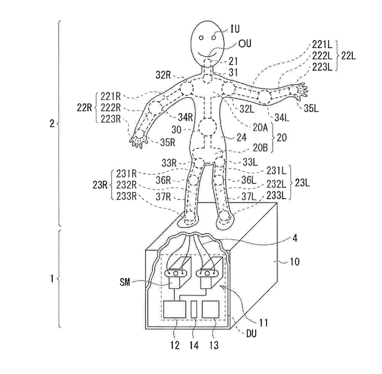
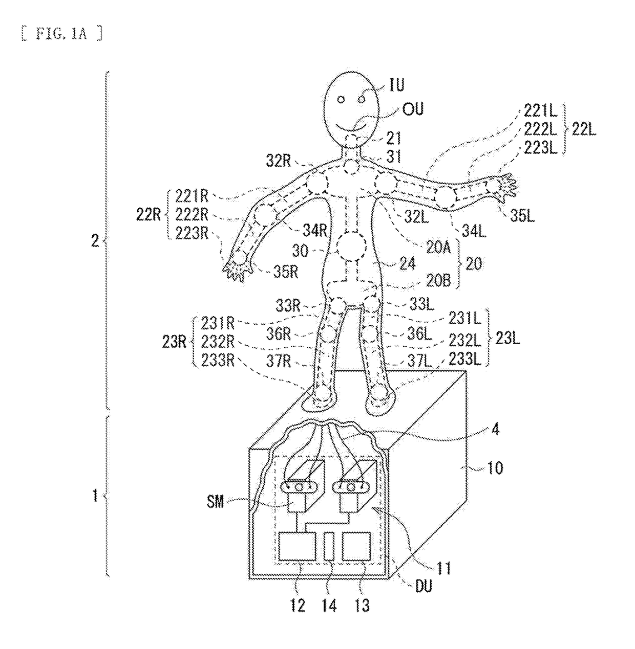
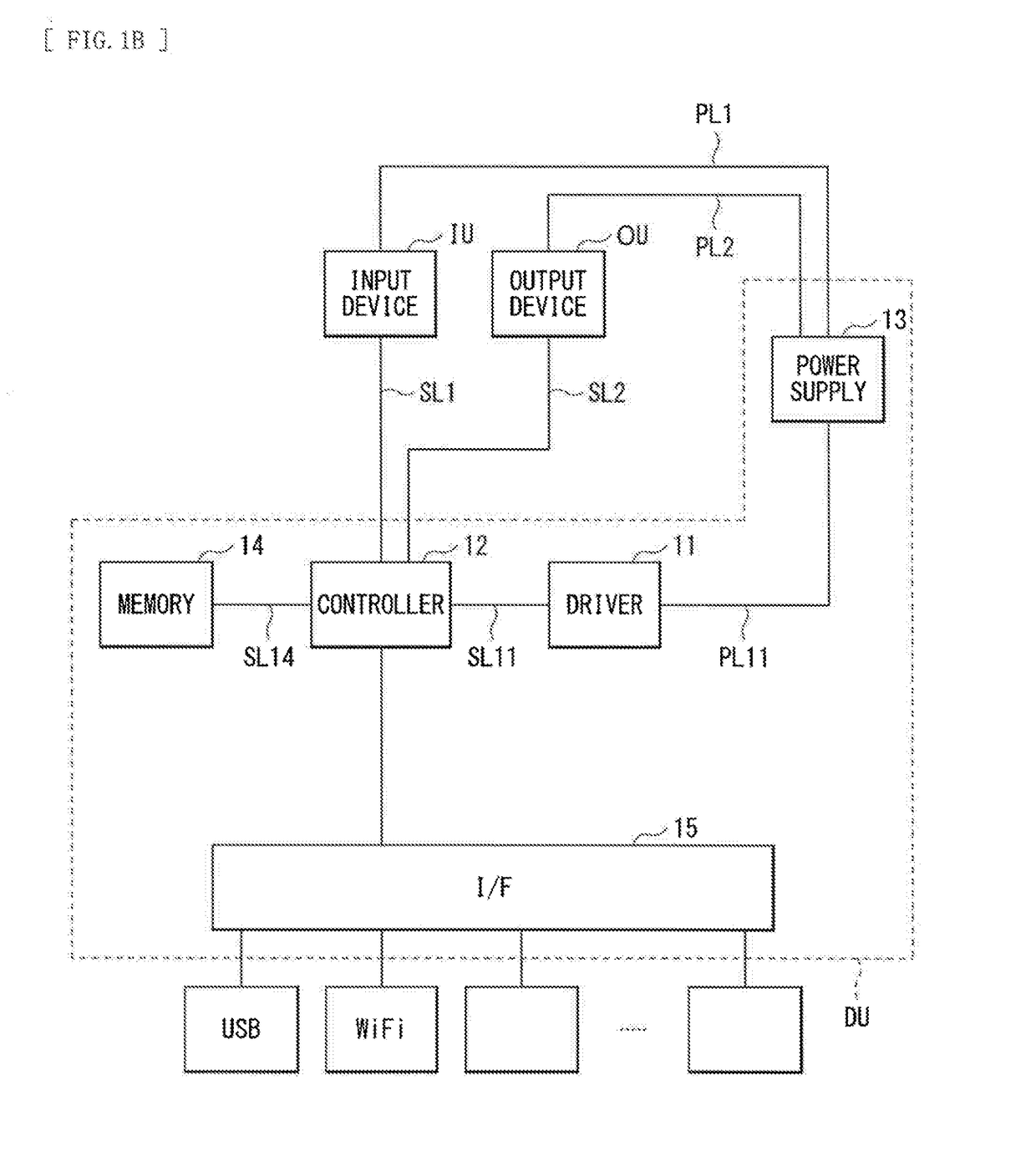
[0123]FIG. 1A is a conceptual diagram schematically illustrating an overall configuration of a figure according to an embodiment of the disclosure. FIG. 1B is a block diagram for describing an internal mechanism of the figure according to the present embodiment. FIG. 1C is a from view of a framework inside the figure according to the present embodiment. FIG. 1D illustrates an example appearance of the figure according to the present embodiment upon its operation.

[0124]Referring to FIG. 1A, the figure according to the present embodiment includes a base 1 and a figure 2 disposed on the base 1.

[0125]Referring to FIG. 1A and FIG. 1C, the figure 2 may include, as its bone members, a torso 20, a head 21, a right arm 22R, a left arm 22L, right leg 23R, and a left leg 23L, for example. The bone members each may be made of a high-stiffness material having a shape such as a plate shape and a rod shape. A cross-section orthogonal to a longitu...

modification examples of first embodiment

Modification Example 1-1

[0155]A description is given, with reference to FIG. 4A, FIG. 4B, and FIG. 4C, of a first modification example (modification example 1-1) of the figure according to the foregoing first embodiment. In the present modification example, the wire 4 extends through a tube T and provided for each of the corresponding axial joint mechanisms. Specifically, the pair of wire elements 41A and 41B provided corresponding to the axial joint mechanism 322 is contained in a single tube T1, for example. The tube T1 is provided inside the figure 2. For example, the tube T1 may be provided inside the epithelium 24. The tube T1 may have a region that is fixed to the bone member by an unillustrated holder. The tube T1 may be so provided as to pass through internal space of any bone member in an example where the bone member has the hollow structure. In this case, for example, a region of the lower torso 20B may have a plurality of tube guides TG as holes that penetrate the region...

modification example 1-2

[0161]A description is given, with reference to FIG. 5A, of a second modification example (modification example 1-2) of the figure according to the foregoing first embodiment. In the present modification example, the pair of wire elements that corresponds to any of the axial joint mechanisms so extend that each of those wire elements is provided in the single tube T. Specifically, out of the pair of wire elements 41A and 41B provided corresponding to the axial joint mechanism 322, the wire element 41A is contained in a tube T1A whereas the wire element 41B is contained in a tube T1B, for example. The present modification example makes it possible to prevent the wire elements 41A and 41B from coming into contact with each other, and thereby to perform a motion of the figure 2 more smoothly. The configuration according to the present modification example is preferable especially for the wire element 40 corresponding to the axial joint mechanism to which strong drive force is to be app...


PUM


Abstract

A figure system includes a drive unit and a figure. The drive unit includes a plurality of first actuators. The figure includes a plurality of joints. The joints have one or more axial joint mechanisms. Drive force derived from at least one of the first actuators is transmitted to corresponding at least one of the axial joint mechanisms through a wire. The drive unit includes, as the plurality of first actuators, a plurality of servomotors having respective drive shafts. The figure includes coupler members having respective bearing holes. The bearing holes are detachably coupled to the respective drive shafts of the servomotors, or configured to be detachably coupled to the respective drive shafts of the servomotors. The wire has a first end coupled to corresponding one of the axial joint mechanisms, and a second end coupled to corresponding one of the coupler members.

Description

TECHNICAL FIELD[0001]The disclosure relates to a movable figure system that makes it possible to perform a predetermined motion, and a figure and a base both used for the figure system.BACKGROUND ART[0002]Figures that represent animation characters, athletes, animals, etc., as their motif have been manufactured, sold, etc., as personal luxuries, for example There have been already proposed figures that include drivers and movable parts. For example, reference is made to Patent Literatures 1 and 2.CITATION LISTPatent Literature[0003]Patent Literature 1: Japanese Unexamined Patent Application Publication No. 2003-325992[0004]Patent Literature 2: Japanese Unexamined Utility Model Application Publication No. H05-68594SUMMARY OF INVENTION[0005]However, a doll toy and a doll disclosed respectively in Patent Literatures 1 and 2, etc., are each extremely simple in its motion and each may possibly involve difficulties in increasing a degree of freedom of its motion.[0006]To increase a degree...

Claims


Application Information

Patent Timeline
IPC IPC(8): G09F19/08A63H3/48A63H13/02
CPCG09F19/08G09F2019/086A63H3/48A63H13/02A63H3/50A63H13/04A63H31/10A63H3/20A63H3/36A63H29/00
Inventor KASUGA, TOMOAKI
Owner SPEECYS
Why Eureka
Try Eureka