

Driver circuit
a driving circuit and circuit technology, applied in the field of liquid crystal display, can solve problems such as signal decay in long distance transmission, and achieve the effects of reducing leakage current, stable driving current, and mitigating the problem of signal decay
- Summary
- Abstract
- Description
- Claims
- Application Information
AI Technical Summary
Benefits of technology
Problems solved by technology
Method used
Image

Examples
Embodiment Construction
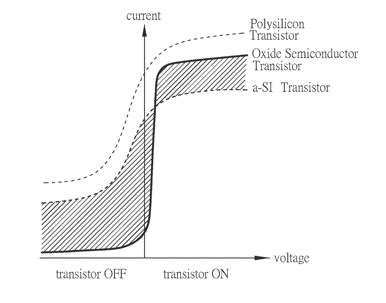
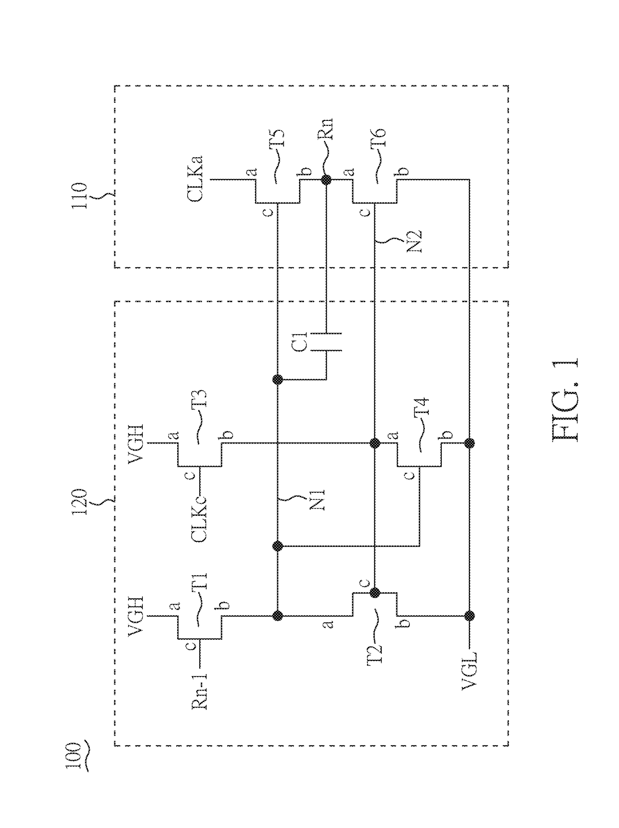
[0023]FIG. 1 is a circuit diagram of a gate line driving circuit 100 according to the present disclosure. As shown in FIG. 1, the driving circuit 100 includes an output circuit 110, and a control circuit 120, which is used to drive a gate line (Rn). The output circuit 110 includes a pull-up transistor (T5) and an auxiliary transistor (T6). The pull-up transistor (T5) and the auxiliary transistor (T6) have a first control node (N1) and a second control node (N2), respectively. The control circuit 120 is coupled to the output circuit 110. The control circuit 120 has a plurality of transistors (T1, T2, T3, T4). The transistors (T1, T2, T3, T4) are connected to the first control node (N1) and the second control node (N2) for controlling the pull-up transistor (T5) and the auxiliary transistor (T6) to be turned on or off. At least one of the transistors (T1, T2, T3, T4) is a transistor with an oxide semiconductor layer, such as an indium-gallium-zinc oxide (IGZO) transistor.
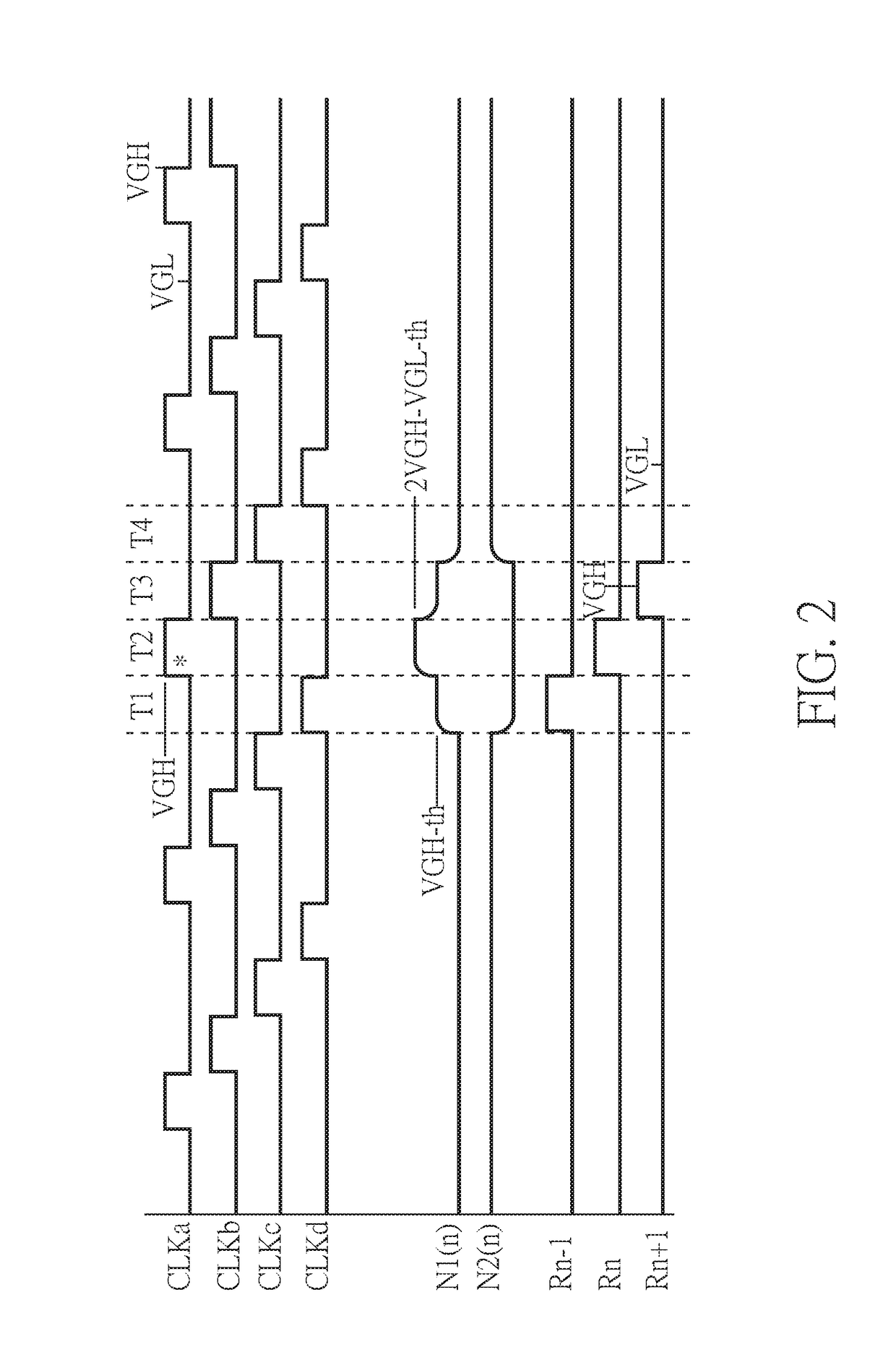
[0024]As show...
PUM
| Property | Measurement | Unit |
|---|---|---|
| voltage | aaaaa | aaaaa |
| voltage | aaaaa | aaaaa |
| semiconductor | aaaaa | aaaaa |
Abstract
Description
Claims
Application Information