
Induction motor rotor and a method of manufacturing the same

a technology of induction motor and rotor, which is applied in the direction of manufacturing cage rotors, magnetic circuit rotating parts, magnetic circuit shape/form/construction, etc., can solve the problems of limiting the high cost of the rotor induction machine of the rotor, and the limitations of the mechanical construction of the rotor, so as to improve the torque output of the induction motor and reduce the cost of the rotor. , the effect o

Active Publication Date: 2017-06-08
ROLLS ROYCE PLC
View PDF3 Cites 9 Cited by
  • Summary
  • Abstract
  • Description
  • Claims
  • Application Information

AI Technical Summary

Benefits of technology

The invention, known as a re-entrant slot geometry, offers a way to keep the materials in place when the motor rotates at high speeds. This allows the motor to operate more efficiently than traditional designs. The sleeve used in the motor is made from copper, which has excellent electromagnetic properties.

Problems solved by technology

The increased complexity of the rotor coils means that wound rotor induction machines are usually significantly more expensive than squirrel cage rotor machines.
However, conventional squirrel cage and wound rotor motor designs have a ceiling peripheral speed of approximately 200 m / s, which is well beneath a theoretical upper limit of approximately 500 m / s.
This is due to the limits of the mechanical construction of the rotors.

Method used


Image

  • Induction motor rotor and a method of manufacturing the same
  • Induction motor rotor and a method of manufacturing the same
  • Induction motor rotor and a method of manufacturing the same

Examples


Embodiment Construction

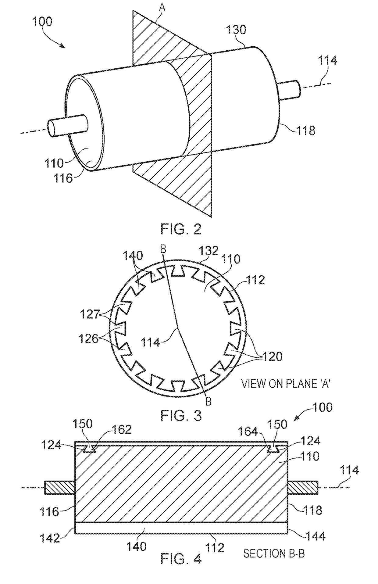
[0113]Referring to FIGS. 2 to 4, an induction motor rotor assembly according to an embodiment of the disclosure is designated generally by the reference numeral 100.

[0114]The induction motor rotor assembly 100 comprises a rotor 110, a sleeve 130 and first and second electrical connection portions 162,164.

[0115]The rotor 110 has a cylindrical geometry with an outer surface 112 and an axis of rotation 114. The rotor also has a first axial end 116 and a second opposite axial end 118.

[0116]The rotor 110 is made from steel. In other arrangements, the rotor 110 may be formed from an alternative material such as, for example, an aluminium alloy or a titanium alloy.

[0117]The rotor 110 comprises a plurality of re-entrant slots 120 machined axially along the outer surface 112 of the rotor 110. In the present embodiment, the cross-sectional profile 126 of each of the re-entrant slots 120 is a dovetail slot 127. In other arrangements of the disclosure, the cross-sectional profile 126 of these r...


PUM

PropertyMeasurementUnit
skew angleaaaaaaaaaa
thickaaaaaaaaaa
speedaaaaaaaaaa

Abstract

A method of manufacturing an induction motor rotor assembly, the method includes the steps of: providing a rotor; machining a plurality of re-entrant slots axially along an outer surface of the rotor; positioning a sleeve concentrically over the outer surface of the rotor; applying a friction stir welding process to the sleeve along each re-entrant slot axially along the outer surface of the rotor to cause the sleeve material to plasticise and flow into the axial re-entrant slot to form an axial re-entrant slot bar; and providing an electrical connection at each of the opposing axial ends of the rotor between respective ones of opposing ends of each of the axial re-entrant slot bars to thereby form the induction motor rotor.

Description

[0001]This disclosure claims the benefit of UK Patent Application No. GB 1521579.1, filed on 8 Dec. 2015, which is hereby incorporated herein in its entirety.FIELD OF THE DISCLOSURE[0002]The present disclosure relates to an induction motor rotor and particularly, but not exclusively, to an induction motor rotor for use with a gas turbine engine, together with a method for manufacturing such an induction motor rotor.BACKGROUND TO THE DISCLOSURE[0003]Induction machines are widely used in motor and generator applications because in conjunction with modern power electronic systems they can provide flexible, efficient and reliable operation to generate and consume electrical power.[0004]Induction motors are an example of asynchronous electrical machines. In an asynchronous machine, the magnetic field in the stator rotates at a speed which is different to the mechanical rotation of the rotor. The difference between these two rotation speeds is called slip.[0005]Induction machines can broa...

Claims


Application Information

Patent Timeline
Patent Type & Authority Applications(United States)
IPC IPC(8): H02K17/16H02K15/09H02K3/48H02K15/02H02K1/26H02K3/32
CPCH02K17/165H02K1/265H02K15/09H02K3/48H02K15/024H02K3/32H02K15/0012B23K20/122H02K17/168
Inventor EMBERTON, JAMESLAMBOURNE, ALEXISCULLEN, JOHN J A
Owner ROLLS ROYCE PLC
Learn More