Heart failure evaluation method and diagnosis device

a technology for applied in the field of heart failure evaluation methods and diagnosis devices, can solve the problems of increasing the frequency of developing acute heart failure, increasing the degree of recovery, and more time for the recovery of cardiac function, so as to achieve accurate and more certain follow-up treatment, the effect of great accuracy

Active Publication Date: 2017-06-15
TEIJIN LTD
View PDF5 Cites 4 Cited by
  • Summary
  • Abstract
  • Description
  • Claims
  • Application Information

AI Technical Summary

Benefits of technology

[0030]According to the present invention, a change in clinical conditions such as exacerbation of clinical conditions of chronic heart failure can be detected with great accuracy and the compensatory mechanism failure of the patient can be predicted at an early stage. In addition, by performing more accurate and more certain follow-up treatment of chronic heart failure, such as further changes in clinical conditions of the patient who falls into a compensatory mechanism failure, it becomes possible to prevent, for example, a patient with acute heart failure from developing chronic heart failure.

Problems solved by technology

Even though the clinical conditions appear to be stable, chronic heart failure progresses, and after passing the duration of SP1, a compensatory mechanism rapidly fails, resulting in the second acute heart failure (t2).
Thus, when acute heart failure develops, gradually more time is required for the recovery of the cardiac function, and the degree of recovery tapers off.
Furthermore, the frequency of developing acute heart failure also increases gradually.

Method used


Image

  • Heart failure evaluation method and diagnosis device
  • Heart failure evaluation method and diagnosis device
  • Heart failure evaluation method and diagnosis device

Examples


first embodiment

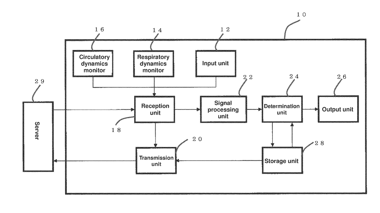
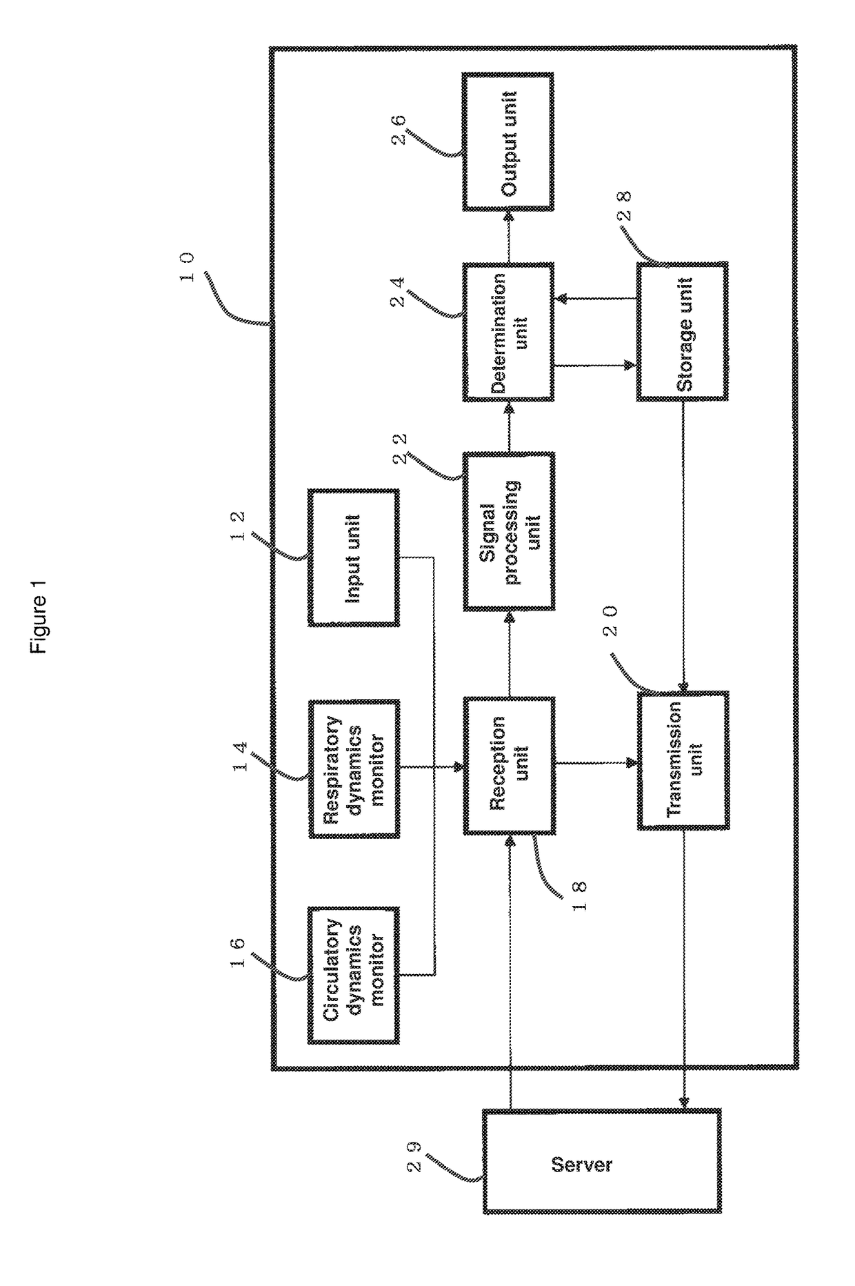
[0079]In FIG. 1, a heart failure diagnosis system 10 consists of an input unit 12, a respiratory dynamics monitor 14, a circulatory dynamics monitor 16, a reception unit 18, a transmission unit 20, a signal processing unit 22, a determination unit 24, an output unit 26 and a storage unit 28 as primary components.

[0080]The input unit 12 can be constituted with a keyboard, a touch panel and others to input necessary orders to the heart failure diagnosis system 10 and edit data stored in the storage unit 28.

[0081]The respiratory dynamics monitor 14 can be constituted with a sensor, an instrument and a system that measure, for example, respiratory frequency and the amount of ventilation of a patient with heart failure, a subject for diagnosis.

[0082]Such a sensor, an instrument and a system may adopt various kinds of methods such as one to detect respiratory gas flow using a respirator equipped with a nasal mask that a patient wears, a temperature sensor or pressure sensor (such as piezo...

second embodiment

[0100]Next, the second embodiment is explained by another look at the present invention according to FIGS. 1, 3 and 4.

[0101]Note that the diagnosis device for heart failure used in the present embodiment follows the system 10 explained in the constitution as the first embodiment in FIG. 1, and a constitution such as the detection unit of some physiological indexes not clearly specified in the first embodiment is explained below.

I. Monitor Unit of Each Physiological Index

[0102]In the present embodiment, one or more monitor parts, which are included in the respiratory dynamics monitor 14 and the circulatory dynamics monitor 16 as shown in FIG. 1 and one including anything but those above which is used for the follow-up treatment of the patient with chronic heart failure, detect (and output if needed) the following physiological index.

(1) Monitor Unit Capturing the Augmentation of the Sympathetic Nervous System

[0103]It is known that the augmentation of the sympathetic nervous system ca...


PUM


Abstract

Provided are a means to detect a plurality of dynamics, a processing unit that calculates a temporal change in the detected dynamics, and an evaluation device that determines exacerbation of clinical conditions in heart failure of a patient based on the calculated change in the patient's dynamics over time. The present invention makes it possible to detect, early and with high accuracy, that the onset of acute heart failure is imminent.

Description

TECHNICAL FIELD[0001]The present invention relates to an evaluation method to detect that the onset of acute heart failure is imminent and to a diagnosis device thereof.BACKGROUND ART[0002]Heart failure is a syndrome resulting from a falling of the heart pumping function. There are a wide variety of causes and clinical conditions accompanied with symptoms such as dyspnea, breath shortness, oliguresis, edema at the four limbs and hepatomegaly. When the heart pumping function rapidly falls and symptoms suddenly emerge, the heart failure is named “acute heart failure”. When the acute heart failure is at the stage in which the overall physical status is stable, it is called “chronic heart failure”. More particularly, acute heart failure is defined as “a clinical condition of rapid emergence or exacerbation of signs and symptoms secondary to increased ventricular end-diastolic pressure and decreased perfusion of major organs, which are caused by acute loss of compensation mechanism of th...

Claims


Application Information

Patent Timeline
Patent Type & Authority Applications(United States)
IPC IPC(8): A61B5/02A61B5/08A61B10/00A61B5/0205
CPCA61B5/02A61B10/00A61B5/08A61B5/0205A61B5/7264A61B5/02007A61B5/02028A61B5/021A61B5/02405A61B5/029A61B5/0816A61B5/091A61B5/14542A61B5/4035A61B5/7275A61B2505/07G16H50/30
Inventor MATSUMOTO, SADAYOSHI
Owner TEIJIN LTD
Why Eureka
Try Eureka