Capacitor assembly and related method of forming

a technology of capacitors and components, applied in the direction of capacitors, multiple fixed capacitors, fixed capacitor housings/encapsulations, etc., can solve the problems of capacitor self-heating, thermal degradation of dielectric materials, and severe affecting the heat transfer capability of capacitor assemblies

Active Publication Date: 2017-06-15
GENERAL ELECTRIC CO
View PDF2 Cites 9 Cited by
  • Summary
  • Abstract
  • Description
  • Claims
  • Application Information

AI Technical Summary

Problems solved by technology

Use of such potting compounds severely affects heat transfer capability within the capacitor assembly.
Moreover, under high ripple current condition, low thermal conductivity of the potting compound leads to capacitor self-heating.
Self-heating of the capacitor typically results in thermal degradation of dielectric materials employed in the capacit...

Method used


Image

  • Capacitor assembly and related method of forming
  • Capacitor assembly and related method of forming
  • Capacitor assembly and related method of forming

Examples


Embodiment Construction

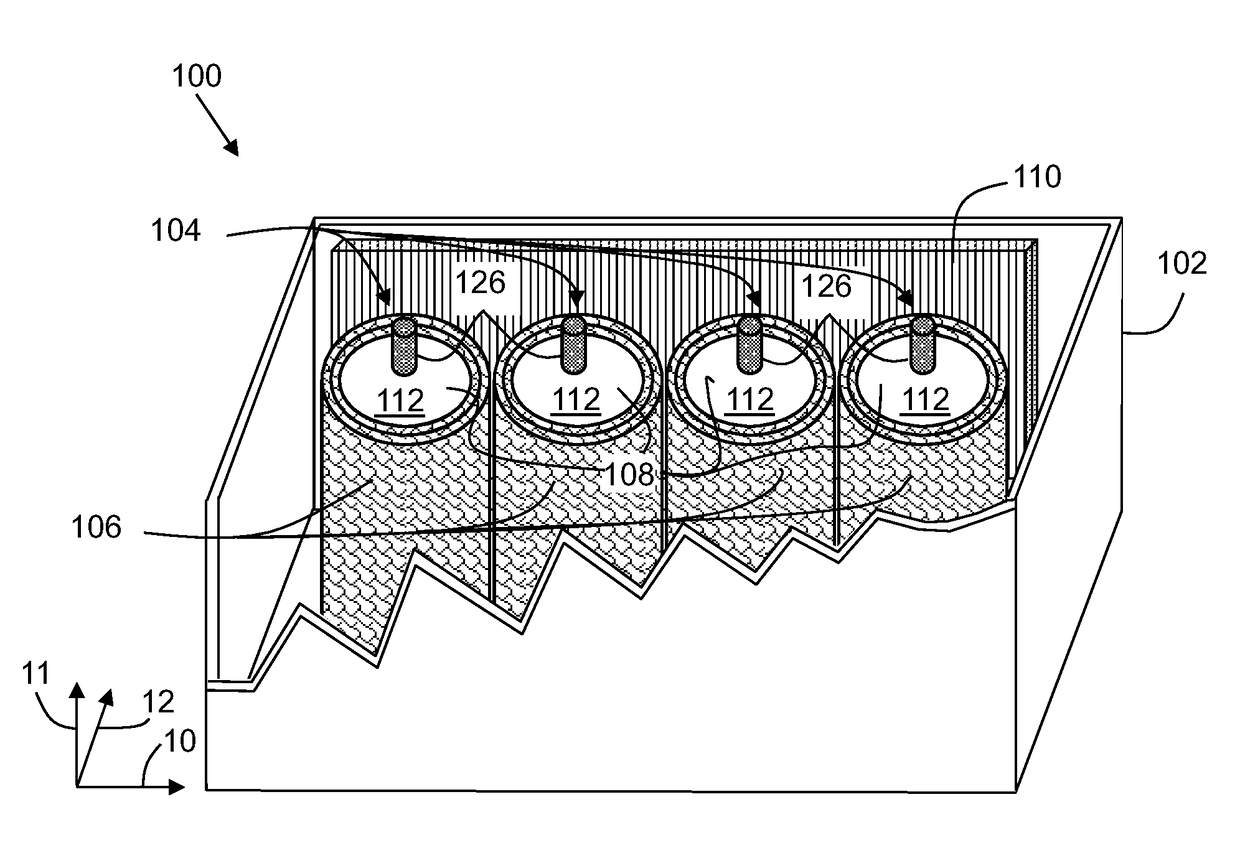
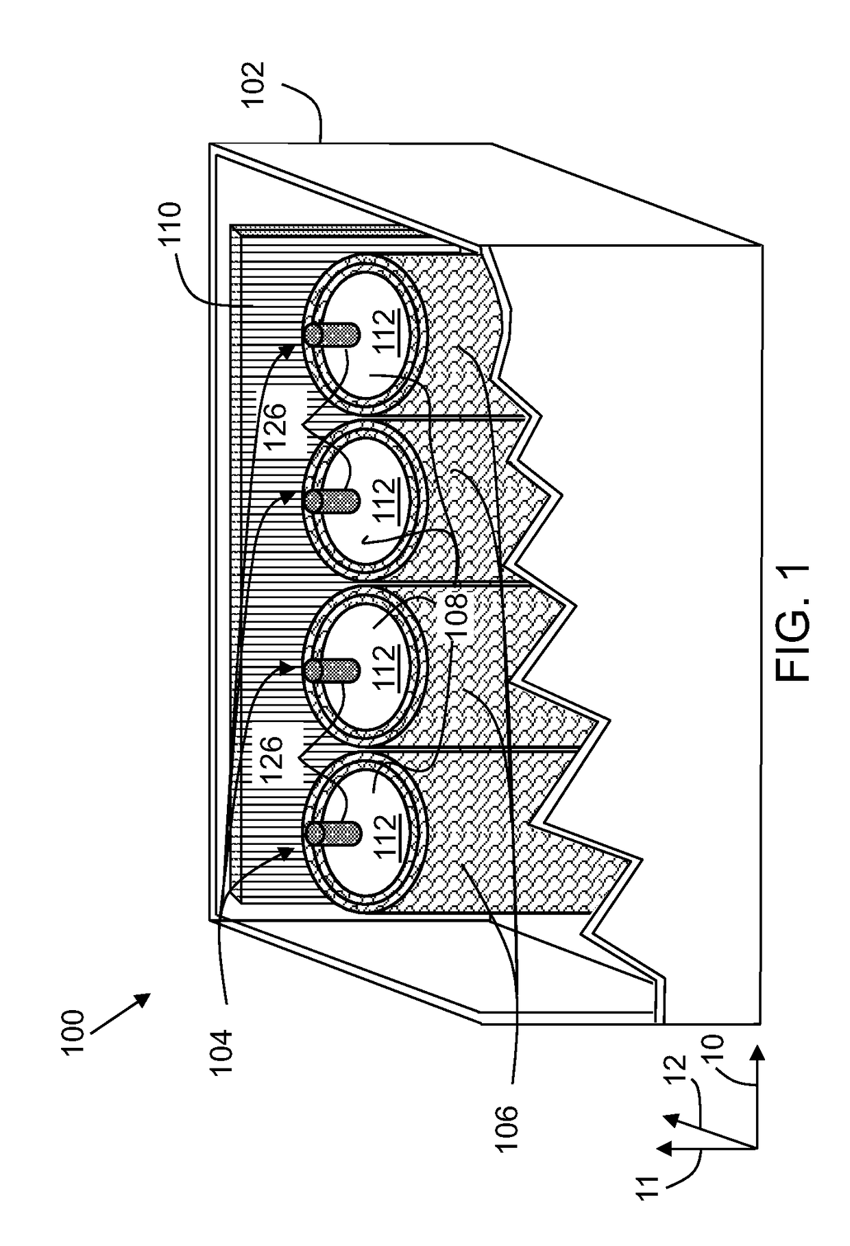
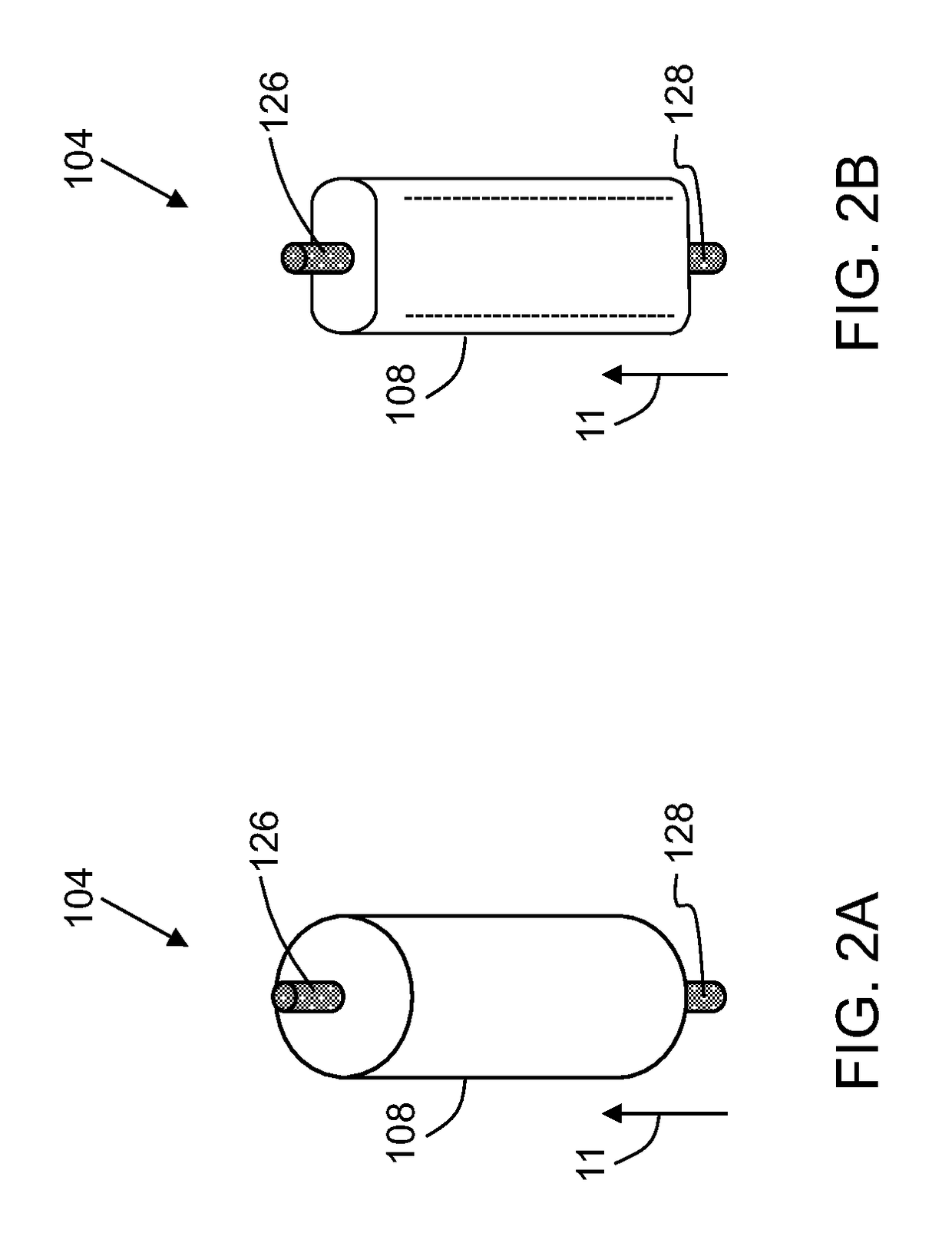
[0017]The specification may be best understood with reference to the detailed figures and description set forth herein. Various embodiments are described hereinafter with reference to the figures. However, those skilled in the art will readily appreciate that the detailed description given herein with respect to these figures is for explanatory purposes as the method and the system may extend beyond the described embodiments.

[0018]Unless defined otherwise, technical and scientific terms used herein have the same meaning as is commonly understood by one of ordinary skill in the art to which this disclosure belongs. In the following specification and the claims, the singular forms “a”, “an” and “the” include plural referents unless the context clearly dictates otherwise. As used herein, the term “or” is not meant to be exclusive and refers to at least one of the referenced components being present and includes instances in which a combination of the referenced components may be presen...


PUM


Abstract

A capacitor assembly is disclosed. The capacitor assembly includes a housing. The capacitor assembly further includes a plurality of capacitors disposed within the housing. Furthermore, the capacitor assembly includes a thermally conductive article disposed about at least a portion of a capacitor body of the capacitors, and in thermal contact with the capacitor body. Moreover, the capacitor assembly also includes a heat sink disposed within the housing and in thermal contact with at least a portion of the housing and the thermally conductive article such that the heat sink is configured to remove heat from the capacitor in a radial direction of the capacitor assembly. Further, a method of forming the capacitor assembly is also presented.

Description

BACKGROUND[0001]Embodiments of the disclosure relate to a capacitor assembly. More particularly, embodiments of the disclosure relate to thermal management of the capacitor assembly and method of forming a capacitor assembly.[0002]Capacitors, at times, need to be operated at increased voltage and current levels. For example, power capacitors are widely used in inverters, typically in a direct current (DC) link of an inverter. Typical rated voltage for such DC-link capacitors ranges from 270 Volts DC to 1100 Volts DC. Additionally, the capacitor is required to deliver current of tens to a few hundred of Amperes.[0003]Therefore, often, a number of capacitors are assembled into a capacitor bank in order to distribute large amplitude of ripple current, or to achieve the desired capacitance. The capacitor bank along with a potting compound is typically encapsulated in a resin to prevent moisture ingress and then sealed in a closed housing, thereby forming a capacitor assembly. Typical po...

Claims


Application Information

Patent Timeline
IPC IPC(8): H01G4/258H01G4/224H01G4/38
CPCH01G4/258H01G4/224H01G4/38H01G2/08H01G4/32
Inventor ZHANG, LILITAN, DANIEL QISULLIVAN, JEFFREY S
Owner GENERAL ELECTRIC CO
Why Eureka
Try Eureka