
Dielectric waveguide

a waveguide and dielectric technology, applied in waveguides, screening casings, electrical equipment, etc., can solve the problems of inter-signal interference, increased crosstalk, undesired electrical effect called dispersion,

Active Publication Date: 2017-06-15
TYCO ELECTRONICS (SHANGHAI) CO LTD +1
View PDF0 Cites 16 Cited by
  • Summary
  • Abstract
  • Description
  • Claims
  • Application Information

AI Technical Summary

Benefits of technology

This patent describes a new type of waveguide that is used to transmit electromagnetic signals. The waveguide has a structure made up of a cladding and a shield that helps to guide the signals. The cladding is made of a specific material and has a hollow core filled with a different material. The cladding also has additional ribs that are attached to its outer surface. The shield is made of a conductive material and surrounds the cladding, creating air gaps between them. The shield has a specific shape and is designed to match the ends of the cladding ribs. The technical effect of this design is that it helps to better control the signals and reduce interference during transmission.

Problems solved by technology

There are several issues associated with portions of the electromagnetic field extending outside of the cladding of the dielectric waveguide into the surrounding environment.
First, the portions of the electromagnetic field outside of the waveguide may produce high crosstalk levels when multiple dielectric waveguides are bundled together in a cable, and the level of crosstalk increases with higher modulated frequencies propagating through the waveguides.
Second, some electromagnetic fields in air may travel faster than fields that propagate within the waveguide, which leads to the undesired electrical effect called dispersion.
Dispersion occurs when some frequency components of a signal travel at a different speed than other frequency components of the signal, resulting in inter-signal interference.
Third, the dielectric waveguide may experience interference and signal degradation due to external physical influences that interact with the electromagnetic field, such as a human hand touching the dielectric waveguide.
Finally, portions of the electromagnetic field outside of the waveguide may be lost along bends in the waveguide, as uncontained fields tend to radiate away in a straight line instead of following the contours of the waveguide.
But, increasing the size of the dielectric waveguide introduces other drawbacks, including reduced flexibility of the waveguides, increased material costs, and a reduced number of waveguides that can fit within a given area or space (for example, reducing the density of waveguides).
But, completely encasing the dielectric waveguide with a conductive material can cause undesirably high energy loss levels (for example, insertion loss and / or return loss) in the waveguides as portions of the electromagnetic fields induce surface currents in the conductive material.
High loss levels shorten the effective length that an electromagnetic wave will propagate through the waveguide.
Furthermore, outer metal shielding layers interacting with the propagating electromagnetic waves can allow undesirable modes of propagation that have hard cutoff frequencies.

Method used


Image

  • Dielectric waveguide
  • Dielectric waveguide
  • Dielectric waveguide

Examples


Embodiment Construction

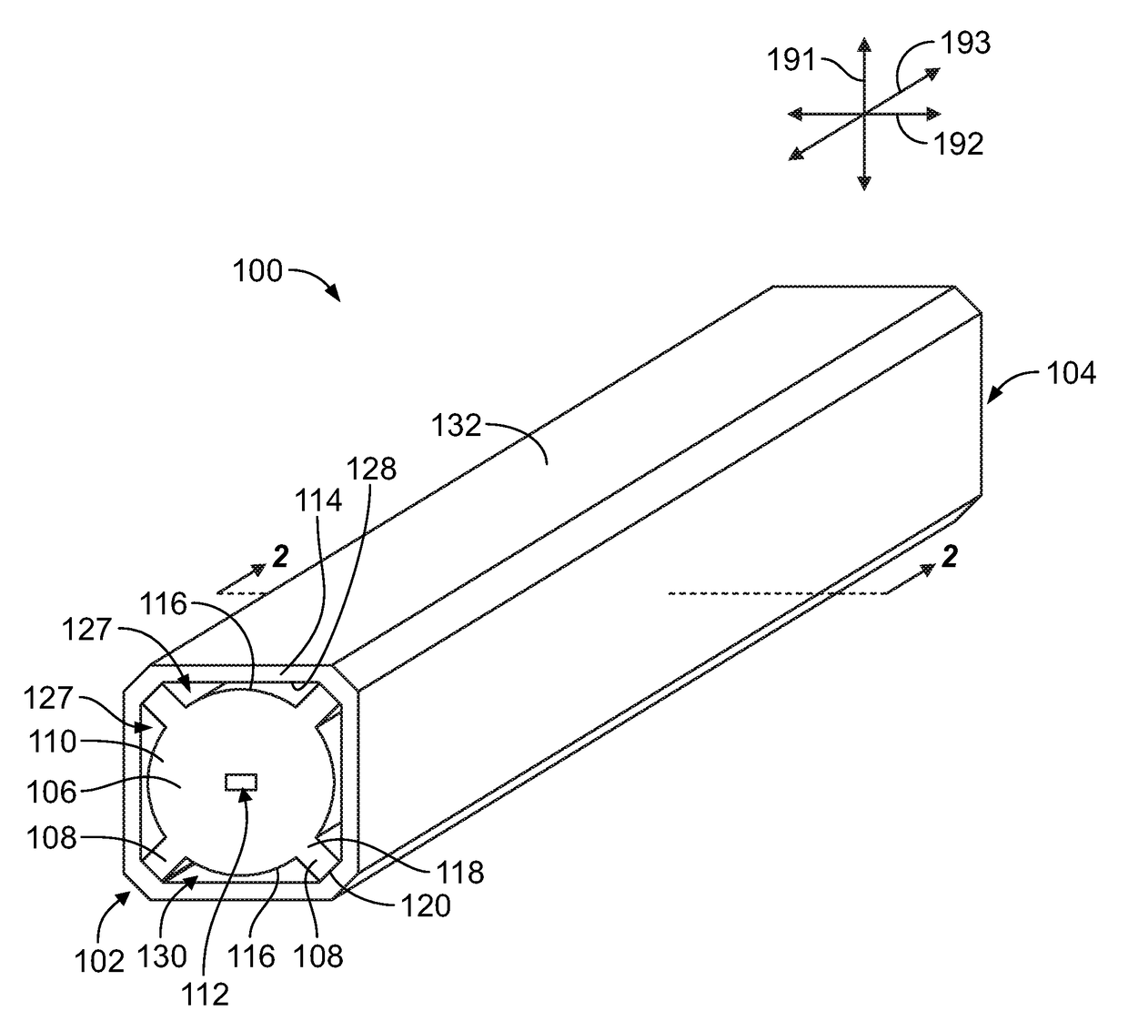
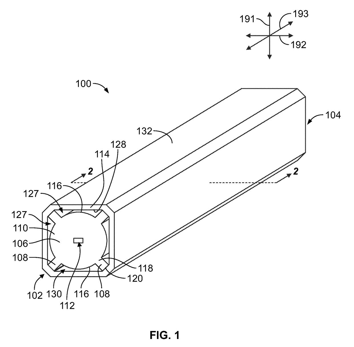
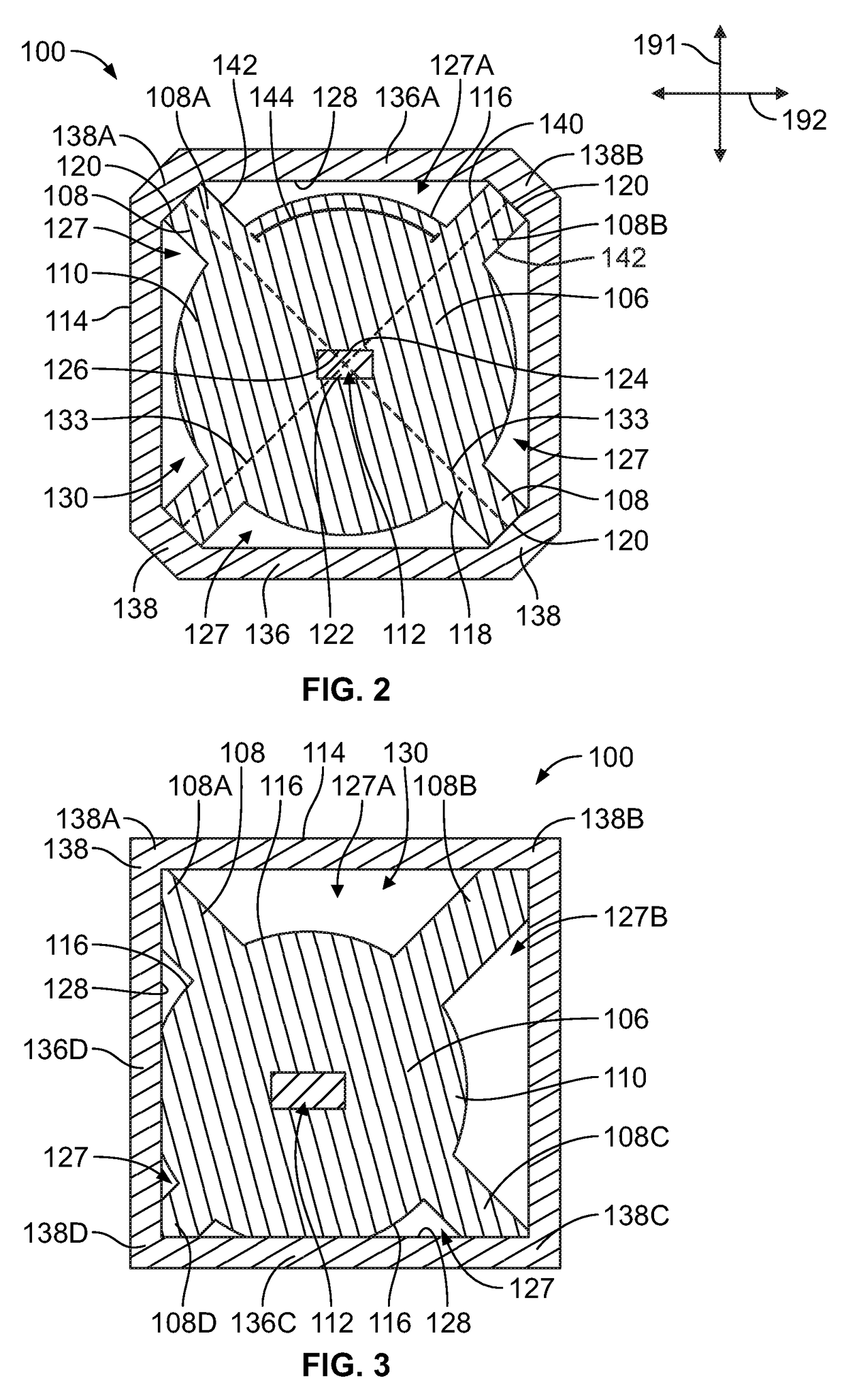
[0018]One or more embodiments described herein are directed to a dielectric waveguide for propagating electromagnetic signals. The embodiments of the dielectric waveguide have a conductive shield placed on the outside of the waveguide in a way to reduce crosstalk and other external interference while at the same time not introducing unwanted mode propagation or undesirably high levels of loss in the waveguide. Lower loss levels allow the waveguides to convey signals farther along a defined path. In one or more embodiments, dielectric extension structures extend beyond a cladding layer and support an electrically conductive shield, such as a metal foil. The extension structures optionally may be extrusion molded as part of the cladding layer of the dielectric waveguide. The extension structures engage and support the shield at locations spaced apart or away from an outer surface or boundary of the cladding such that air-filled gaps or pockets are defined between the cladding and the ...


PUM


Abstract

A dielectric waveguide for propagating electromagnetic signals includes a cladding and an electrically conductive shield. The cladding has a body composed of a first dielectric material. The body defines a core region therethrough that is filled with a second dielectric material different than the first dielectric material. The cladding further includes at least two ribs extending from an outer surface of the body to distal ends. The shield engages the distal ends of the ribs and peripherally surrounds the cladding such that air gaps are defined radially between the outer surface of the body and an interior surface of the shield.

Description

CROSS-REFERENCE TO RELATED APPLICATIONS[0001]This application claims priority to Chinese Patent Application No. 201510922442.6, filed on 14 Dec. 2015, which is incorporated by reference herein in its entirety.BACKGROUND OF THE INVENTION[0002]The subject matter herein relates generally dielectric waveguides.[0003]Dielectric waveguides are used in communications applications to convey signals in the form of electromagnetic waves along a path. Dielectric waveguides provide communication transmission lines for connecting communication devices, such as connecting an antenna to a radio frequency transmitter and / or receiver. Although waves in open space propagate in all directions, dielectric waveguides generally confine the waves and direct the waves along a defined path, which allows the waveguides to transmit high frequency signals over relatively long distances.[0004]Dielectric waveguides include at least one dielectric material, and typically have two or more dielectric materials. A d...

Claims


Application Information

Patent Timeline
Patent Type & Authority Applications(United States)
IPC IPC(8): H01P3/16H05K9/00
CPCH05K9/0049H01P3/16H01P3/122H01P3/123H01P3/127
Inventor MORGAN, CHAD WILLIAMHUANG, LIANG
Owner TYCO ELECTRONICS (SHANGHAI) CO LTD
Learn More