Check patentability & draft patents in minutes with Patsnap Eureka AI!

Rotor alignment for reducing vibrations and noise

a rotor and noise technology, applied in the direction of electrical equipment, supports/enclosements/casings, dynamo-electric machines, etc., can solve the problems of electric motors, in particular, in synchronous resistance technology, frequently subjected to vibration and noise, vibration and noise is generally disruptive, etc., to achieve small air gap, small air gap, and greater differentiation

Active Publication Date: 2017-06-15
SIEMENS AG
View PDF0 Cites 4 Cited by
  • Summary
  • Abstract
  • Description
  • Claims
  • Application Information

AI Technical Summary

Benefits of technology

The invention is about a device that aligns the magnets in a motor. One advantage is that it prevents the rotor from moving too close to the stator when aligning them. This is important because it helps avoid damage to the motor. This limit on the rotor's movement is especially important when the rotor is only able to move a small distance in a radial direction.

Problems solved by technology

Electric motors, in particular, in synchronous-reluctance technology, are frequently subjected to vibrations and noise during operation due to asymmetries.
Such vibrations and noise are generally disruptive for the intended use, but also for the operating personnel.
However, not only electric motors, but in some circumstances, generators are also affected by asymmetries.
The causes of these asymmetries firstly result from manufacturing inaccuracies.
Further, inaccuracies may result generally from components such as the housing, stator, bearing shield, bearings and rotor of the electrical machine.
The material properties are typically not considered in an ideal alignment of the rotor axis.

Method used


Image

  • Rotor alignment for reducing vibrations and noise
  • Rotor alignment for reducing vibrations and noise
  • Rotor alignment for reducing vibrations and noise

Examples


Embodiment Construction

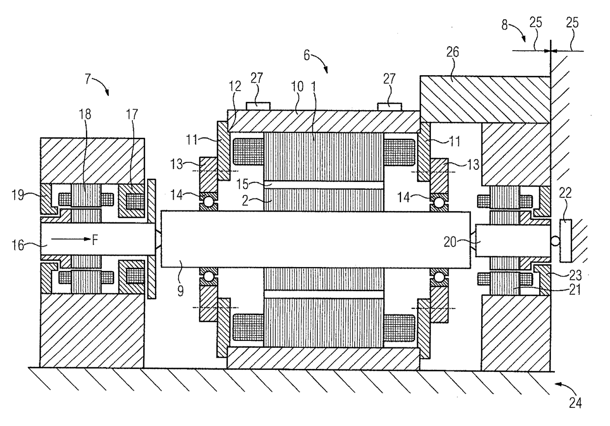
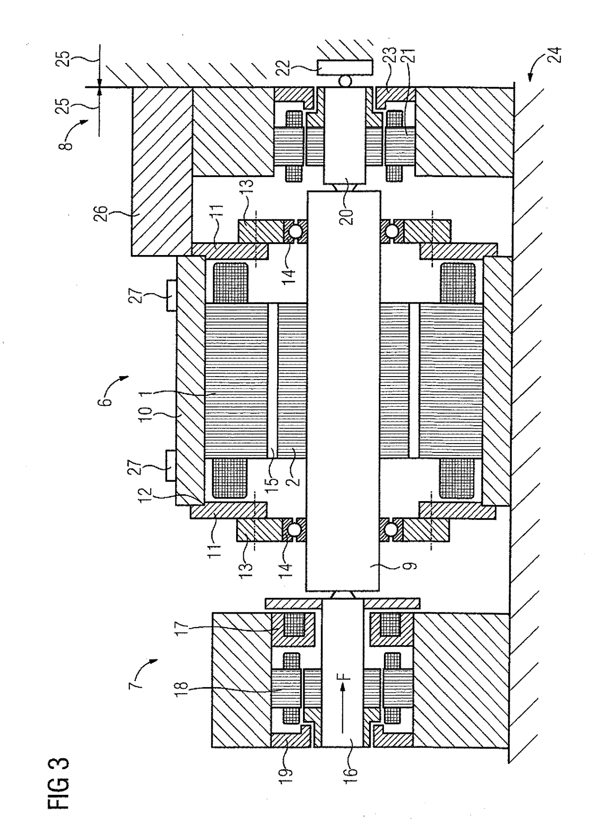
[0028]Throughout the figures, same or corresponding elements may generally be indicated by same reference numerals. These depicted embodiments are to be understood as illustrative of the invention and not as limiting In any way. It should also be understood that the figures are not necessarily to scale and that the embodiments are sometimes illustrated by graphic symbols, phantom lines, diagrammatic representations and fragmentary views. In certain instances, details which are not necessary for an understanding of the present invention or which render other details difficult to perceive may have been omitted.

[0029]The exemplary embodiments described in more detail hereinafter represent preferred embodiments of the present invention. It should be noted that the individual features may be implemented not only in the combinations set forth but also in other technically expedient combinations or separately.

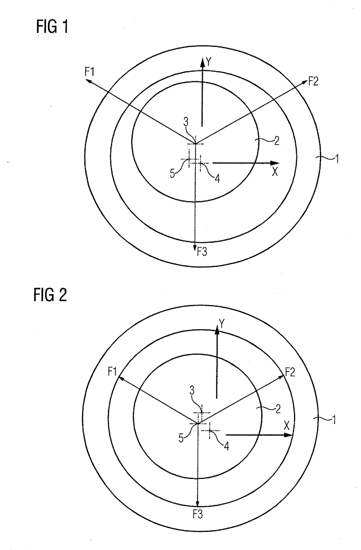
[0030]Turning now to the drawing to FIG. 1, there is shown schematically a force ...


PUM


Abstract

For reducing vibrations and noise in electrical machines a rotor is mounted in a magnetic alignment device while a bearing shield is loosely held relative to a stator. The rotor is driven by the stator and vibrations of the rotor are detected. A magnetic alignment device is controlled so as to reduce the vibrations. Finally the bearing shield is fixed to the stator in a position determined by the controlling of the magnetic alignment device. Thus electromagnetic forces are taken into consideration during vibration and noise reduction.

Description

CROSS-REFERENCES TO RELATED APPLICATIONS[0001]This application claims the priority of European Patent Application, Serial No. 15199807.7, filed Dec. 14, 2015, pursuant to 35 U.S.C. 119(a)-(d), the content of which is incorporated herein by reference in its entirety as if fully set forth herein.BACKGROUND OF THE INVENTION[0002]The invention relates to a method for mounting a rotor in a stator of an electrical machine, and to a mounting system for mounting such a rotor in a stator.[0003]The following discussion of related art is provided to assist the reader in understanding the advantages of the invention, and is not to be construed as an admission that this related art is prior art to this invention.[0004]Electric motors, in particular, in synchronous-reluctance technology, are frequently subjected to vibrations and noise during operation due to asymmetries. Such vibrations and noise are generally disruptive for the intended use, but also for the operating personnel. Therefore, atte...

Claims


Application Information

Patent Timeline
IPC IPC(8): H02K5/15H02K7/09H02K5/24
CPCH02K5/15H02K7/09H02K5/24H02K15/165
Inventor BUTTNER, KLAUSKIRCHNER, KLAUSWARMUTH, MATTHIASWOHNER, NORBERT
Owner SIEMENS AG
Features
  • R&D
  • Intellectual Property
  • Life Sciences
  • Materials
  • Tech Scout
  • Unparalleled Data Quality
  • Higher Quality Content
  • 60% Fewer Hallucinations
Learn More