Amplifier circuit and voltage regulator

a voltage regulator and amplifier circuit technology, applied in the direction of electric variable regulation, process and machine control, instruments, etc., can solve the problems of phase delay, negative feedback circuit with high risk of oscillation, phase delay, etc., to improve phase characteristics, improve phase characteristics, and reduce the effect of phase delay of feedback voltag

Active Publication Date: 2017-06-15
ABLIC INC
View PDF8 Cites 24 Cited by
  • Summary
  • Abstract
  • Description
  • Claims
  • Application Information

AI Technical Summary

Benefits of technology

[0017]According to the amplifier circuit capable of improving the phase characteristics, and the voltage regulator including the amplifier circuit of the present invention, there is provided a signal propagation path formed by the capacitor configured to generate a phase lead current. As a result, the phase delay of the feedback voltage may be alleviated. Thus, there can be provided the amplifier circuit capable of lowering a risk that the negative feedback circuit may oscillate and improving the phase characteristics, and the voltage regulator including the amplifier circuit.

Problems solved by technology

However, in the related-art negative feedback amplifier circuit 500, there is a problem in that a phase of a feedback voltage is delayed due to a pole appearing in output of an amplifier circuit, and that a negative feedback circuit thus has a high risk of oscillating.
For example, when the load capacitance is small and the load resistance is small, the pole appears at a high frequency and causes a phase delay.
Further, for example, when the load capacitance is large and the load resistance is large, the pole appears at a low frequency and causes a phase delay.

Method used


Image

  • Amplifier circuit and voltage regulator
  • Amplifier circuit and voltage regulator
  • Amplifier circuit and voltage regulator

Examples


Embodiment Construction

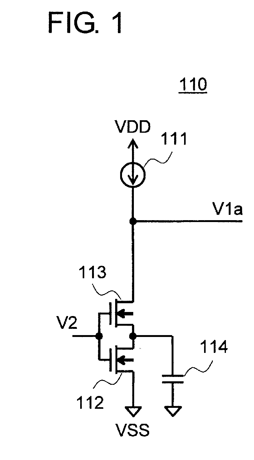
[0023]FIG. 1 is a circuit diagram for illustrating an example of an amplifier circuit according to an embodiment of the present invention.

[0024]In FIG. 1, an amplifier circuit 110 of this embodiment includes a current source 111, NMOS transistors 112 and 113, and a capacitor 114.

[0025]The NMOS transistor 112 has a source connected to a ground terminal (VSS), and a gate connected to an input terminal of the amplifier circuit 110. The NMOS transistor 113 has a source connected to a drain of the NMOS transistor 112, and a gate connected to the input terminal of the amplifier circuit 110. The current source 111 is connected between a power supply terminal (VDD) and a drain of the NMOS transistor 113. The capacitor 114 is connected between the source of the NMOS transistor 113 and the ground terminal. The amplifier circuit 110 has an output terminal connected to the drain of the NMOS transistor 113.

[0026]An operation of the amplifier circuit 110 of this embodiment is described.

[0027]A vo...


PUM


Abstract

Provided are an amplifier circuit capable of improving phase characteristics, and a voltage regulator including the amplifier circuit. The amplifier circuit is configured to amplify an input voltage and to output the input voltage, and includes a current source, a first transistor having a gate to which the input voltage is applied, and a second transistor having a gate to which a voltage synchronous with the input voltage is applied, and a source connected to a capacitor.

Description

RELATED APPLICATIONS[0001]This application claims priority under 35 U.S.C. §119 to Japanese Patent Application No. 2015-242546 filed on Dec. 11, 2015, the entire content of which is hereby incorporated by reference.BACKGROUND OF THE INVENTION[0002]1. Field of the Invention[0003]The present invention relates to an amplifier circuit capable of improving phase characteristics, and a voltage regulator including the amplifier circuit.[0004]2. Description of the Related Art[0005]FIG. 5 is a circuit diagram of a related-art negative feedback amplifier circuit.[0006]A related-art negative feedback amplifier circuit 500 includes an amplifier circuit 510, which is a common source amplifier circuit, and an amplifier circuit 520. The amplifier circuit 510 includes a current source 511 and an NMOS transistor 512, which are connected in series.[0007]The amplifier circuit 510 has an output connected to an input of the amplifier circuit 520. The amplifier circuit 520 has an output connected to a ga...

Claims


Application Information

Patent Timeline
Patent Type & Authority Applications(United States)
IPC IPC(8): H02M3/158H03F1/34
CPCH02M3/158H03F2200/69H03F1/342G05F1/561G05F1/468G05F1/56H03F3/505H03F2203/5036H03F1/223H03F2200/297H03G3/12
Inventor SUGIURA, MASAKAZU
Owner ABLIC INC
Why Eureka
Try Eureka