High-frequency millimeter wave low-profile transmission array antenna

An array antenna, millimeter wave technology, applied in antennas, antenna arrays, space feed arrays, etc., to achieve good transmission performance and reduce the size of the antenna

Active Publication Date: 2022-05-17
UNIV OF ELECTRONICS SCI & TECH OF CHINA
View PDF7 Cites 0 Cited by
  • Summary
  • Abstract
  • Description
  • Claims
  • Application Information

AI Technical Summary

Problems solved by technology

However, due to the limitation of resonance conditions, the traditional PRS array bandwidth is only about 2%

Method used


Image

  • High-frequency millimeter wave low-profile transmission array antenna
  • High-frequency millimeter wave low-profile transmission array antenna
  • High-frequency millimeter wave low-profile transmission array antenna

Examples


Embodiment

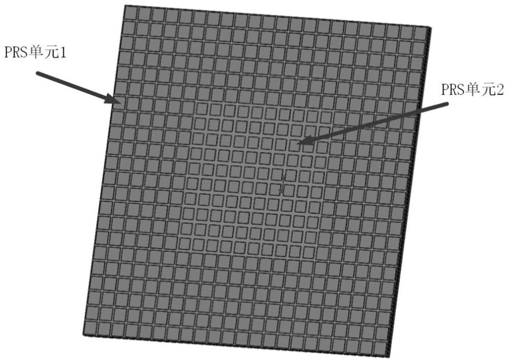
[0117] Such as figure 1 As shown, it is a schematic diagram of the structure of the PRS front, including PRS unit 1 and PRS unit 2. The center of the PRS front is 100 PRS units 2 arranged in 10×10, and the edge of the PRS front is 384 PRS units 1, in the form of 22 ×22 planar arrangement, and remove 100 units in the center.

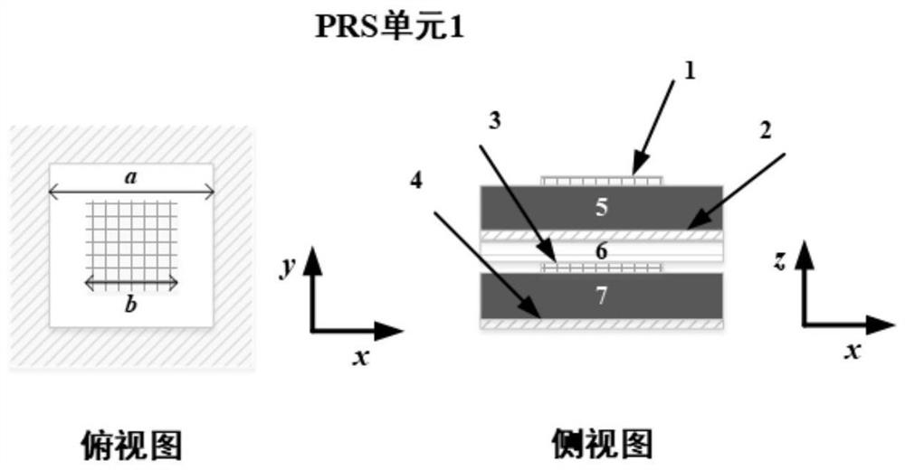
[0118] Wherein, the structure of the PRS unit 1 is as follows figure 2 As shown, it includes a dielectric substrate 5, an adhesive layer 6, a metal patch 1 located on the upper surface of the dielectric substrate 5, a metal patch 3 located between the adhesive layer 6 and the dielectric substrate 7, and a dielectric substrate 5 and the adhesive layer. 6 between the metal ring 2 and the metal ring 4 located on the lower surface of the dielectric substrate 7; one side of the metal patch 1 is parallel to one side of the dielectric substrate 5, and the center coincides with the center of the dielectric substrate 5; One side of the metal patch 3 is paralle...


PUM


Abstract

The invention discloses a high-frequency millimeter wave low-profile transmission array antenna, and belongs to the technical field of millimeter wave array antennas. The high-frequency millimeter wave low-profile transmission array antenna comprises a feed source, a PRS array plane located right above the feed source and a transmission array plane located right above the PRS array plane. According to the high-frequency millimeter wave low-profile transmission array antenna provided by the invention, the transmission array plane with a specific structure and arrangement mode is combined with the PRS array plane with a specific structure and arrangement mode, so that the gain fluctuation of the obtained transmission array antenna is less than 3dB and the relative bandwidth is 9.3% within the range of 95.3 GHz to 104.6 GHz; in the 3dB gain bandwidth, the s11 in the range of 95.3 GHz to 95.8 GHz is less than-9dB, and the s11 of other frequency points is less than-10dB; within the range of 95.3 GHz to 104.6 GHz, beam scanning of +/-40 degrees is realized in a two-dimensional space.

Description

technical field [0001] The invention belongs to the technical field of millimeter-wave array antennas, in particular to a broadband low-profile transmission array antenna for high-frequency millimeter-waves. Value. Background technique [0002] As an important working frequency band for future millimeter-wave communications, the high-frequency millimeter-wave frequency band can meet the needs of communication and other electronic devices for wider bandwidth and higher information transmission rates. However, in the high-frequency millimeter-wave frequency band, the large space loss of electromagnetic waves and the approximate linear propagation characteristics make the spatial coverage of the signal a shackle that limits the scale of high-frequency millimeter-wave commercial use. [0003] As a high-gain beam-scanning antenna, the transmissive array antenna integrates space feeding and phase modulation technology. By precisely adjusting the state of each transmission unit, t...

Claims


Application Information

Patent Timeline
Patent Type & Authority Applications(China)
IPC IPC(8): H01Q21/00H01Q1/38H01Q1/48H01Q19/06H01Q19/185
CPCH01Q21/0018H01Q19/06H01Q19/185H01Q1/48H01Q1/38Y02D30/70
Inventor 姜昊张健张鲁明杨帆陈飞良李沫
Owner UNIV OF ELECTRONICS SCI & TECH OF CHINA
Why Eureka
Try Eureka