Vehicular cooling system

a cooling system and vehicular technology, applied in the direction of electric propulsion mounting, machine/engine, vehicle sub-unit features, etc., can solve the problems of large number of parts included in the respective cooling circuit and large size of the cooling system as a whole, so as to reduce the size of the cooling system and ensure both cooling performance and lubrication performance. , the effect of reducing the number of parts

Inactive Publication Date: 2017-06-22
TOYOTA JIDOSHA KK
View PDF0 Cites 45 Cited by
  • Summary
  • Abstract
  • Description
  • Claims
  • Application Information

AI Technical Summary

Benefits of technology

[0010]The present disclosure provides a vehicular cooling system enabling reduction in size of a cooling system and ensuring both cooling performance and lubrication performance.
[0034]In the above aspect, the oil circulation circuit includes the first circuit (cooling circuit) including the inverter and the electric motor, and the second circuit (lubrication circuit) including the lubrication-required part. Since the oil circulation circuit circulates the oil alone, the vehicular cooling system can be downsized compared to conventional cases where an inverter cooling circuit that circulates cooling water and a transaxle cooling circuit that circulates oil are separate from each other. Also, the first circuit can supply the oil cooled by the oil cooler to the inverter and the electric motor, and the second circuit can supply the oil that has not passed through the oil cooler, to the lubrication-required part. Consequently, the cooling system can ensure both cooling performance and lubrication performance.

Problems solved by technology

Thus, the number of parts included in the respective cooling circuits is large and the cooling system has a large size as a whole.

Method used


Image

  • Vehicular cooling system
  • Vehicular cooling system
  • Vehicular cooling system

Examples


first embodiment

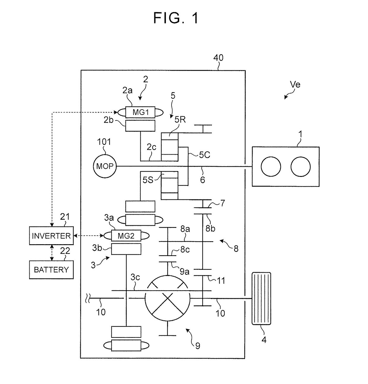
[0048][1. Vehicle]FIG. 1 is a skeleton diagram illustrating an example of a vehicle with a vehicular cooling system installed therein. A vehicle Ve is a hybrid vehicle including an engine 1, a first motor (MG1) 2 and a second motor (MG2) 3 as motive power sources. The engine 1 is a publicly-known internal combustion engine. The motors 2, 3 are publicly-known motor-generators having a motor function and an electric power generation function. The respective motors 2, 3 are electrically connected to a battery 22 via an inverter 21. Also, the respective motors 2, 3 are included in a cooling-required part in the transaxle case 40. The inverter 21 is disposed outside the transaxle case 40.

[0049]The vehicle Ve includes a power dividing mechanism 5 in a power transmission path from the engine 1 to wheels (drive wheels) 4. In the vehicle Ve, motive power output by the engine 1 is divided to the first motor 2 side and the wheels 4 side by the power dividing mechanism 5. At this time, the firs...

second embodiment

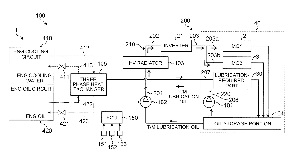
[0101]Next, a cooling system 100 according to a second embodiment will be described with reference to FIGS. 6 to 9. The cooling system 100 according to the second embodiment is different from the first embodiment in including a three phase heat exchanger that causes heat exchange among engine cooling water (hereinafter referred to as “ENG cooling water”), engine oil (hereinafter referred to as “ENG oil”) and T / M lubricating oil (hereinafter referred to as “T / M oil”). In the description of the second embodiment, description of components that are similar to those of the first embodiment will be omitted and for such components, the reference numerals used in the first embodiment are used.

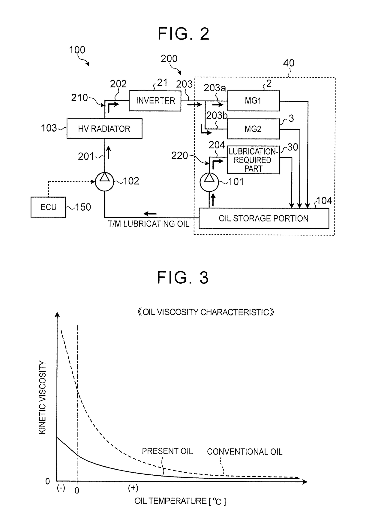
[0102][5. Cooling system]FIG. 6 is a schematic diagram illustrating a schematic configuration of the cooling system 100 according to the second embodiment. As illustrated in FIG. 6, the cooling system 100 according to the second embodiment includes a three phase heat exchanger (hereinafter simply refe...


PUM


Abstract

An cooling system including an oil circulation circuit includes a first circuit including an electric oil pump that discharges oil as a coolant to be supplied to an inverter and respective motors, and an HV radiator that cools the oil to be supplied to the inverter and the respective motors, and a second circuit including a mechanical oil pump that discharges the oil to be supplied to a lubrication-required part without passing through the HV radiator.

Description

INCORPORATION BY REFERENCE[0001]The disclosure of Japanese Patent Application No. 2016-239824 filed on Dec. 9, 2016 including the specification, drawings and abstract is incorporated herein by reference in its entirety.BACKGROUND[0002]1. Technical Field[0003]The present disclosure relates to a vehicular cooling system.[0004]2. Description of Related Art[0005]As cooling systems for hybrid vehicles with an engine and electric motors installed therein, inverter cooling circuits for cooling an inverter electrically connected to the electric motors are known. It is known that the inverter cooling circuits circulate cooling water (hybrid cooling water) as a coolant.[0006]Also, engine cooling circuits using cooling water (engine cooling water) that is different from hybrid cooling water as a coolant are publicly known. Japanese Patent Application Publication No. 2013-199853 discloses a cooling system including an engine cooling circuit, and a transaxle cooling circuit using oil as a coolan...

Claims


Application Information

Patent Timeline
Patent Type & Authority Applications(United States)
IPC IPC(8): F01P7/14F01P3/18
CPCF01P7/14F01P3/18F01P2050/24F01P2007/146F01P2060/045F01P2003/008B60K11/02F16H57/0413B60K1/00B60K1/02B60K7/0007B60K17/145B60K2001/006B60K2007/0061B60Y2200/92B60Y2400/73B60K6/445Y02T10/62B60K6/20
Inventor TOKOZAKURA, DAISUKEARAKAWA, KAZUYASHIINA, TAKAHIRO
Owner TOYOTA JIDOSHA KK
Why Eureka
Try Eureka