Fuel reducing clutch control apparatus and method for fuel reduction using the same

a technology of clutch control and fuel reduction, which is applied in the direction of clutches, control devices, non-mechanical actuated clutches, etc., can solve the problems of increasing the initial purchase price, aggravate the fatigue of the driver, and strain on the driver's knees and waste, so as to improve the fuel efficiency of the vehicle, reduce the operation error, and reduce the effect of fuel reduction

Inactive Publication Date: 2017-06-22
WONKWANG E&TECH
View PDF2 Cites 0 Cited by
  • Summary
  • Abstract
  • Description
  • Claims
  • Application Information

AI Technical Summary

Benefits of technology

[0028]According to the present disclosure, miniaturization of machinery is achieved and an operational error is reduced by using a non-contact type displacement detection system using a position detecting sensor for a clutch clearance, the operation of an actuator is regulated using a plurality of solenoid valves, as a result, allowing accurate position control of a pneumatic cylinder which operates the clutch, thereby improving fuel efficiency of vehicle and achieving fuel reduction.
[0029]The present disclosure provides an optimal driving environment for fuel efficiency improvement by transmitting and receiving data related with vehicle speed, engine rotation frequency, amounts of fuel supply and clutch pedal to / from an ECU of vehicle via CAN communication, and collecting accurate position information through a clutch switch, a clutch pedal operation sensor, and an actuator position sensor to regulate the driving mode in real time.
[0030]Furthermore, there is an effect on the provision of a clutch control apparatus that achieves simple attachment and detachment to / from existing vehicles, provides convenient maintenance and repair of products, and allows beginner drivers to easily manipulate.
[0031]In addition, as opposed to earlier technology, there are effects on miniaturization of machinery and reduction in operational error by using a non-contact type displacement detection system using a straight line distance sensor such as a PSD sensor for a clutch clearance.

Problems solved by technology

However, the clutch must operate the clutch pedal numerously while the car stops and goes at low speeds repeatedly for a long time or drives in city, which aggravates fatigue of the driver and places strain on the driver's knees and waste.
Also, to avoid stalling the car, when the driver takes his / her foot off the clutch pedal, the driver needs to step on the accelerator pedal with a delicate foot motion for a half clutch period, and in this instance, if the driver takes his / her foot off the clutch pedal prematurely, the car shakes or the engine stalls, and on the contrary, if the driver takes his / her foot off the clutch pedal too late, power is not properly transmitted to the car, resulting in failure to driving control of the car.
To solve this inconvenience, an automatic transmission achieving automatic shifting is mounted, and in this case, advantages are convenience and comfort the driver feels during driving, but disadvantages are increases in initial purchasing price, and increased fuel consumption by about 20-30% during driving as compared to a manual transmission.
In the case of existing commercial manual cars, when the foot is taken off the accelerator pedal during driving, fuel is supplied to the engine and consumed in proportion to the driving speed (RPM), and as a solution for reducing fuel, coasting in neutral on a hill is considered, but there are inherent problems with accident risks, for example, non-application of engine braking and stopping distance.
To solve this problem, many concepts of semi-auto clutches have been proposed, but their structure is complex, causing the problem with subsequent repair and maintenance, and process of attaching to existing cars is complex.
Particularly, in the case of conventional semi-auto clutches, as a clutch operation is controlled using a motor, its rotation value is read from a potentiometer and converted to a straight line displacement value, and a clutch clearance is calculated and used for transmission control, and to this end, machinery size increases, making it difficult to mount in cars.
Furthermore, unnecessary transmission impacts occur due to an error through mechanical SLIP in the process of converting the rotation value to displacement.

Method used


Image

  • Fuel reducing clutch control apparatus and method for fuel reduction using the same
  • Fuel reducing clutch control apparatus and method for fuel reduction using the same
  • Fuel reducing clutch control apparatus and method for fuel reduction using the same

Examples


Embodiment Construction

[0039]Hereinafter, the present disclosure will be described in detail with reference to the accompanying drawings.

[0040]Rather, in the description of the present disclosure, when a certain detailed description of related known functions or configuration is deemed to render the nature of the present disclosure ambiguous, its detailed description is omitted herein. Prior to the description, it should be noted that even though the same term is used, different reference symbols may be used if the same term indicates different components.

[0041]In addition, the terms used herein are set in consideration of functionality in the present disclosure, and may be changed as intended by users such as experimenters or measurers or according to custom, and thus each term should be defined based on the disclosure throughout the specification.

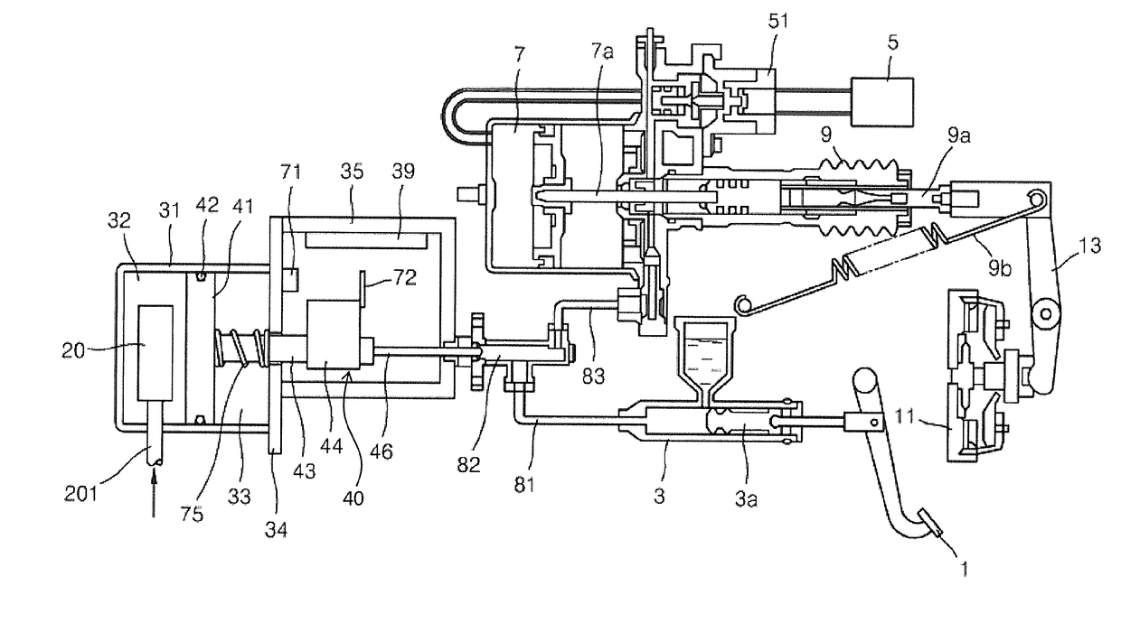
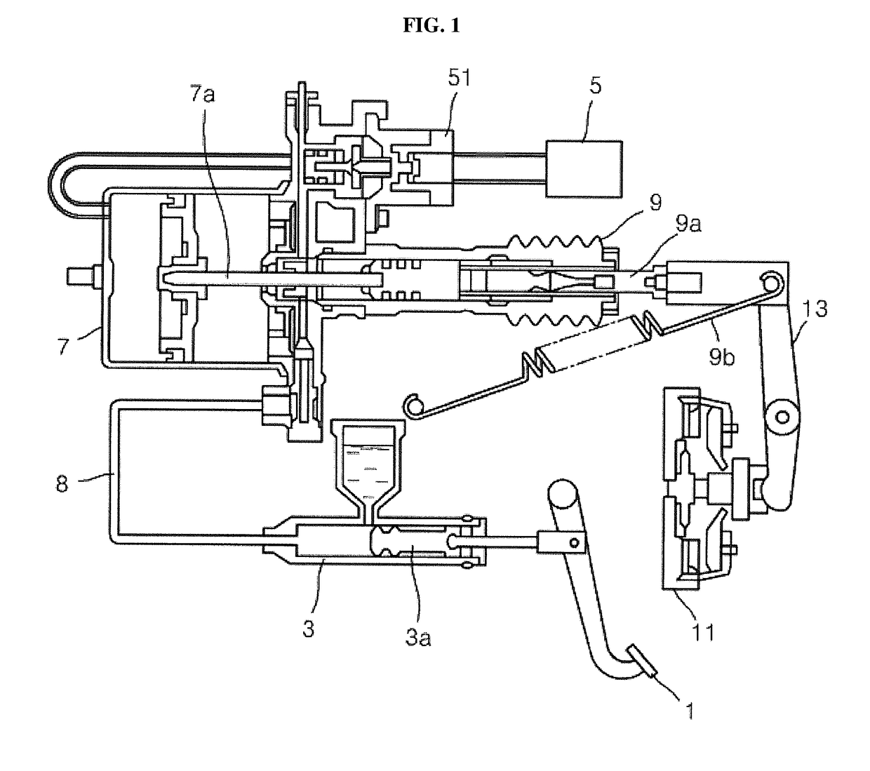
[0042]FIG. 2 is a diagram showing that a clutch control apparatus according to the present disclosure is coupled to an existing clutch. Rather, the diagram was...


PUM


Abstract

The present disclosure relates to a clutch control apparatus, and more particularly, to a clutch control apparatus that achieves miniaturization of machinery and reduces an operational error by using a non-contact type displacement detection system using a position detecting sensor for a clutch clearance, and regulates the operation of an actuator using a plurality of solenoid valves, as a result, allowing accurate position control of a pneumatic cylinder which operates the clutch, thereby improving fuel efficiency and achieving fuel reduction as well as reducing emissions of carbon dioxide.

Description

TECHNICAL FIELD[0001]The present disclosure relates to a fuel reducing clutch control apparatus, and more particularly, to a clutch control apparatus that achieves miniaturization of machinery and reduces an operational error by using a non-contact type displacement detection system using a position detecting sensor for a clutch clearance, and regulates the operation of an actuator using a plurality of solenoid valves, as a result, allowing accurate position control of a pneumatic cylinder which operates the clutch, thereby reducing fuel consumption and emissions of carbon dioxide.BACKGROUND ART[0002]A clutch is a device that connects and disconnects a pair of concentric rotary shafts easily and rapidly. The clutch is generally between a motor and an input shaft transmitted to a machine to operate or stop the machine, and causes an engine to operate in non-load state as in cars.[0003]A clutch used in commercial cars has a power transmission function to transmit a rotating force of t...

Claims


Application Information

Patent Timeline
Patent Type & Authority Applications(United States)
IPC IPC(8): F16D48/06F16D48/02B60K23/02
CPCF16D48/066F16D25/14B60K23/02F16D48/06F16D2048/0212F16D2500/1026F16D2500/3026F16D2500/3108F16D2500/3124F16D2500/31413F16D2500/31426F16D2500/3144F16D2500/5043F16D2500/5085F16D2500/70406
Inventor LEE, DONG GEUNBAEK, BYEONG CHEOLLEE, SEONG CHEOLKIM, SEONG JIN
Owner WONKWANG E&TECH
Why Eureka
Try Eureka