
System comprising a cellular network of capacitive pressure and shear-stress sensors and manufacturing process

Active Publication Date: 2017-06-22
FEETME
View PDF10 Cites 40 Cited by
  • Summary
  • Abstract
  • Description
  • Claims
  • Application Information

AI Technical Summary

Benefits of technology

The sensor network system described in this patent allows for high-resolution measurements of forces applied to a network of sensors using a minimally invasive and cost-effective manufacturing method. This system can measure friction forces and has a small thickness and high sensitivity. The method uses a low-accuracy process and avoids the use of liquid-phase chemical components, making it more efficient and suitable for integration onto flexible materials. Overall, this system has a wide range of applications and improved precision in force measurement.

Problems solved by technology

However, such a sensor provides no pressure measurements spatially resolved on the surface of the sensor.
Moreover, this capacitive pressure sensor does not allow discriminating a normal pressure from a pressure induced by a shear force.
However, the integration of a great number of capacitive pressure sensors to manufacture a high-spatial-resolution sensor network has for drawback to require a far greater number of electrical connections connecting the sensor network to the measurement system.
A drawback of the method of manufacturing of the dual-level printed circuit is that it requires a greater number of steps of manufacturing.
Moreover, this method requires a rigid printed circuit substrate, which may suit for tactile applications, but generally do not suit for an application to a sole with pressure sensors.
Finally, the interconnections between two levels of electrodes deposited on a deformable substrate are fragile and may create electrical faults.
On the other hand, a drawback of the capacitive sensors based on deformable dielectric materials is that the deformation thereof generally shows hysteresis, liable to induce measurement errors.
Moreover, the capacitive shear-force sensors have a lower sensitivity than the normal pressure sensors.

Method used


Image

  • System comprising a cellular network of capacitive pressure and shear-stress sensors and manufacturing process
  • System comprising a cellular network of capacitive pressure and shear-stress sensors and manufacturing process
  • System comprising a cellular network of capacitive pressure and shear-stress sensors and manufacturing process

Examples


Embodiment Construction

[0044]The present invention also relates to the characteristics that will be revealed in the following description and that will have to be considered in isolation or according to any technically possible combination thereof.

[0045]This description, given by way of non-limitative example, will allow a better understanding of how the invention may be performed in reference with the appended drawings, in which:

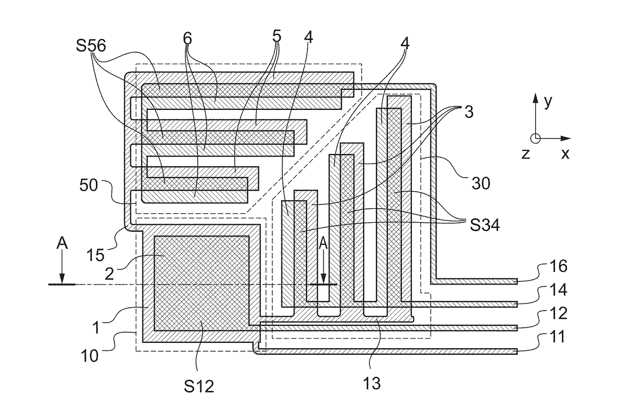
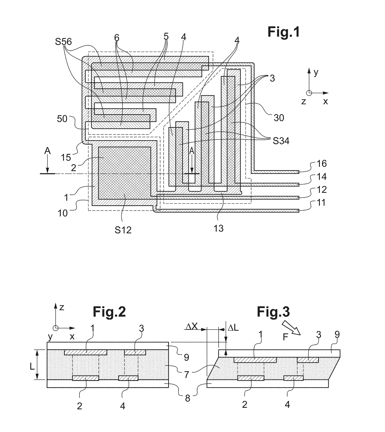
[0046]FIG. 1 schematically shows a top view of a capacitive pressure sensor cell according to an embodiment of the invention;

[0047]FIG. 2 schematically shows a sectional view along the line AA of the capacitive pressure sensor cell of FIG. 1;

[0048]FIG. 3 illustrates the capacitive pressure sensor cell of FIG. 2, subjected to a shear force applied in the direction of axis X;

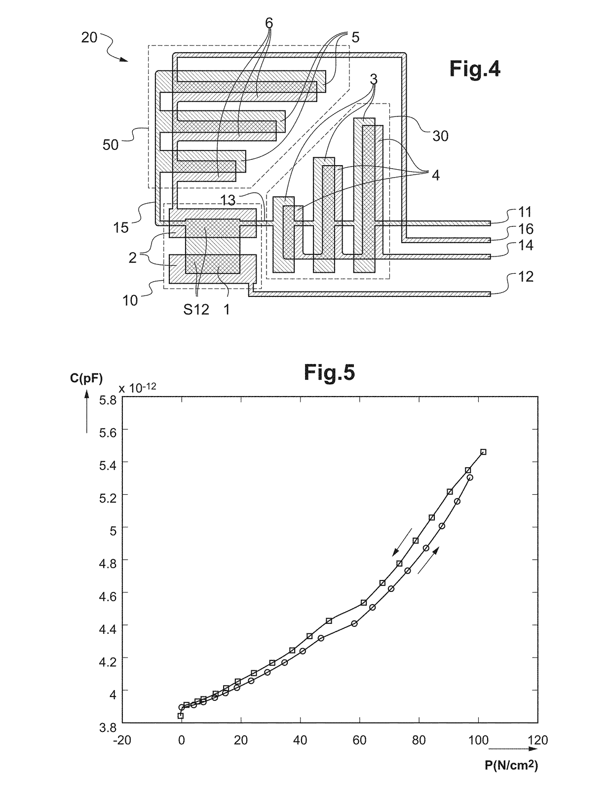
[0049]FIG. 4 schematically shows a top view of a capacitive pressure sensor according to a variant of the invention;

[0050]FIG. 5 shows a measurement of normal pressure force by applying an increasing then decre...


PUM


Abstract

Disclosed is a system and to a process for manufacturing a system including a network of sensors including a sheet of dielectric material that is elastically deformable under compressive and shear stress, each cell of the network including a first capacitive sensor for sensing normal pressure in a first direction, a second capacitive sensor for sensing shear stress in a second direction and a third capacitive sensor for sensing shear stress in a third direction. Each capacitive sensor includes a first electrode fixed to the first side of the sheet of dielectric material and a second electrode fixed to the second side of the sheet of dielectric material, the first electrodes of the capacitive sensors of a given cell being connected in series to a first electrically conductive track connecting a row of cells of the network of sensors.

Description

TECHNICAL FIELD[0001]The present invention relates to a sensor network system for measuring pressure forces with a high spatial resolution. A pressure force can generally be broken into, on the one hand, a compressive force that is applied perpendicular to the surface of the pressure sensor, and on to the other hand, a shear force that is applied in an oblique direction with respect to the surface of the pressure sensor.[0002]More precisely, the invention relates to a sole with pressure sensors intended to measure compressive and shear forces with a high spatial resolution. The invention also relates to various methods of manufacturing a pressure sensor network system.TECHNOLOGICAL BACKGROUND[0003]In the medical field or the sport field, it is desirable to know the distribution of the pressure forces exerted by the feet of a person, in static or dynamic position. In the medical field, a sole with pressure sensors finds applications as a diagnostic sole in podology or orthopedics. Da...

Claims


Application Information

Patent Timeline
IPC IPC(8): G01L1/14A61B5/103
CPCG01L1/142A61B5/1036G01L1/00A43B3/0005G01L5/167G01N2203/0025G01L1/2287G01L1/146G01L5/165A43B17/00G01D5/2412A43B3/34A43B3/44
Inventor MATHIEU, ALEXISMERCIER, JULIEN
Owner FEETME
Learn More