Fast high-resolution microscopy method and fast high-resolution microscope

a high-resolution microscopy and high-resolution technology, applied in the field of high-speed high-resolution localization microscopy of specimens, can solve the problems of not being very to not at all suitable for living specimens, requiring many individual images of specimens, and requiring too much at the expense of localization accuracy, so as to improve the ratio of signal to background radiation, reduce the stress of specimen photos, and fast refresh rate

Active Publication Date: 2017-06-22
CARL ZEISS MICROSCOPY GMBH
View PDF1 Cites 7 Cited by
  • Summary
  • Abstract
  • Description
  • Claims
  • Application Information

AI Technical Summary

Benefits of technology

[0023]2. For conventional fluorophores and thus for the vast majority of usual applications of fluorescence microscopy, the probability of transition into the dark state is, as mentioned, dependent on the intensity of the excitation radiation; the bright time and thus the blinking frequency change inversely with respect to each other. The more intensive the excitation radiation is, the more fluorophores pass into the dark state and the shorter the bright time (higher the blinking frequency) is. The blinking frequency can therefore be set appropriately with simple optical means and adapted to the need of the camera. By increasing the blinking frequency, the period that a molecule is in the bright state decreases. Although the dark state remains unchanged in length since it is preferably the natural dark state that has a fixed molecule-specific lifetime. The ratio between bright time and dark time is thus controlled in that the dark state becomes longer relative to the bright time. On a relative scale, a result is thus achieved that was only possible in the state of the art with chemical manipulation, i.e. extension of the dark state.
[0024]3. By referring to the blinking frequency, the present invention achieves an advantageous utilization of the interaction of integration time / image frequency of the camera and intensity of the excitation radiation, with the result that conventional fluorophores, which had been not available in PALM, can be used for localization microscopy without chemical influence.
[0026]5. Reference to the blinking frequency ensures that precisely one dark state of a blinking molecule is contained in every individual image since the refresh rate of the individual images is not lower than the blinking frequency. This frequency is composed from one bright state and one dark state. The localization of the corresponding molecule is thus still possible with conventional methods. The localization analysis of the microscopy method according to the present invention does not fundamentally differ therefore from that of standard PALM or modifications thereof. However, since the fluorescence emitters of the specimen emit several photons during their bright time, each molecule is now detected by several photons. This provides an advantageous compensation for the integration time which is comparatively short compared with the state of the art and is adapted to the blinking frequency. The relatively rapid image capture surprisingly does not lead to a poorer signal / noise ratio in the localization analysis.
[0032]In particularly preferred embodiments the fluorescence emitters are in a chemically unaffected state with respect to the lifetime of their dark state. This is of particular advantage in live-cell microscopy since a chemical effect on living cells is generally very disadvantageous. The present invention adapts the power of the excitation radiation to the refresh rate. This is advantageous in particular for live-cell microscopy since the photon stress of the specimen is reduced at quicker refresh rates.
[0033]The microscopic setup corresponds to that of a typical widefield fluorescence microscope, with the control device now adapted to control the excitation device and the imaging device to adjust the excitation intensity and refresh rate to each other. The excitation radiation can illuminate the specimen in form of continuous radiation (CW radiation). For fluorescence measurements, a pulsed excitation and an operation of the camera synchronized thereto is preferred. This synchronized operation can also be used in order to improve a ratio of signal to background radiation for emitters of individual molecules, namely when a background autofluorescence of a considerably different lifetime of the dark state and / or of the bright state, for example with a considerably longer or considerably shorter lifetime, is present in the specimen.
[0034]The invention aligns the refresh rate of the camera and the blinking frequency of the specimen to each other. There are certain advantages in setting the blinking frequency and thus the refresh rate relatively high. Then, the integration time of the camera is comparatively short. Some embodiments using a high refresh rate to utilize a SPAD detector array in the camera. It is therefore preferred for the camera to comprise a SPAD array.

Problems solved by technology

However, it requires many individual images of the specimen to be captured which in each case contain isolated molecules.
Capturing time is also a problem for localization microscopy in that widefield detection, which is advantageous in and of itself, necessarily also requires a two-dimensional detector which must be sufficient sensitive to the detection of individual molecules.
However, in the case of current microscopy methods, this would be too much at the expense of localization accuracy.
These dyes are not very to not at all suitable for living specimens.
In addition, here too there is the problem of a long measurement length since a certain minimum number of individual images are required for a relevant increase in resolution.
In addition, the possible increase in resolution is limited compared with localization microscopy.

Method used


Image

  • Fast high-resolution microscopy method and fast high-resolution microscope
  • Fast high-resolution microscopy method and fast high-resolution microscope
  • Fast high-resolution microscopy method and fast high-resolution microscope

Examples


Embodiment Construction

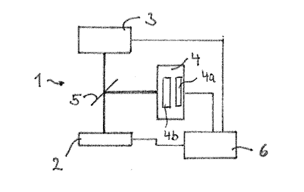
[0049]FIG. 1 shows a microscope 1 schematically that images a specimen 2 in high resolution. Here, the term high resolution is used, as is usual in the state of the art, for an imaging method that has a spatial resolution that has increased beyond the diffraction limit of the imaging. The microscope 1 serves to image a specimen 2 that contains fluorescence emitters. By means of radiation from an illumination source 3, the fluorescence emitters are excited to emit fluorescent radiation. The fluorescing specimen 2 is imaged onto a widefield camera 4 via a beam splitter 5. The operation of the microscope 1 is controlled by a control device 6 that is connected to the widefield camera 4, the illumination source 3 and optionally a table on which the specimen 2 is located via corresponding control lines (not further identified) and that actuates these elements or receives data from them, in particular image data from the widefield camera 4.

[0050]In an embodiment, the widefield camera 4 com...


PUM

PropertyMeasurementUnit
integration timeaaaaaaaaaa

Abstract

A fast, high-resolution localization microscopy method for a specimen containing fluorescence emitters. In a bright state, emitters emit fluorescent radiation upon excitation irradiation, and in a dark state, the fluorescence emitters do not emit fluorescent radiation upon excitation irradiation. The emitters can be brought from the bright state into the dark state by irradiation, and the dark state has a lifetime after which the emitters return to the bright state spontaneously, such that the emitters blink at a blinking frequency. The blinking specimen is imaged with a spatial resolution and detected with a camera, the intensity of the radiation is set such that emitters are isolated in the individual images in terms of the spatial resolution, and the refresh rate at which the images are produced is not lower than the blinking frequency. Locations are determined for isolated emitters in the images with an accuracy that exceeds the spatial resolution.

Description

PRIORITY CLAIM[0001]The present application claims priority to German Patent Application No. 102015105673.9, filed on Apr. 14, 2015, which said application is incorporated by reference in its entirety herein.FIELD OF THE INVENTION[0002]The invention relates to a method for high-speed high-resolution localization microscopy of a specimen containing fluorescence emitters in which the fluorescence emitters in the specimen are excited to emit fluorescent radiation and the specimen is imaged in the widefield with a spatial resolution, the excitation is effected such that at least some fluorescence emitters are isolated in terms of spatial resolution, and in a localization analysis locations are determined for the isolated fluorescence emitters with an accuracy which exceeds the spatial resolution.[0003]The invention further relates to a high-resolution microscope for high-speed localization microscopy of a specimen containing fluorescence emitters that comprises an excitation device, whi...

Claims


Application Information

Patent Timeline
Patent Type & Authority Applications(United States)
IPC IPC(8): G01N21/64
CPCG01N21/6458G02B21/0004G02B21/16G02B21/367
Inventor KALKBRENNER, THOMAS
Owner CARL ZEISS MICROSCOPY GMBH
Why Eureka
Try Eureka