Gate in Panel (GIP) Driving Circuit and Display Device Using the Same

a driving circuit and display device technology, applied in static storage, digital storage, instruments, etc., can solve the problems of not being able to reduce the size the components or lines required for a stable operation of the gip driving circuit cannot be removed, and it is not easy to efficiently design the bezel area of the display device, etc., to achieve the effect of simplifying the gate driving circui

Active Publication Date: 2017-06-22
LG DISPLAY CO LTD
View PDF2 Cites 9 Cited by
  • Summary
  • Abstract
  • Description
  • Claims
  • Application Information

AI Technical Summary

Benefits of technology

The present invention describes a way to simplify the circuit that controls the display on a screen by using two inverters connected in a feedback way. This helps to create a narrower bezel for the display device.

Problems solved by technology

As a result, it is not easy to efficiently design a bezel area of a display device.
However, the components or lines required for a stable operation of a GIP driving circuit cannot be removed.
Thus, a size of the GIP driving circuit cannot be reduced.
Therefore, it is difficult to design a narrow bezel of a display device due to a size of a GIP circuit.

Method used


Image

  • Gate in Panel (GIP) Driving Circuit and Display Device Using the Same
  • Gate in Panel (GIP) Driving Circuit and Display Device Using the Same
  • Gate in Panel (GIP) Driving Circuit and Display Device Using the Same

Examples


Embodiment Construction

[0034]Advantages and features of the present disclosure, and methods for accomplishing the same will be more clearly understood from exemplary embodiments described below with reference to the accompanying drawings. However, the present disclosure is not limited to the following exemplary embodiments but may be implemented in various different forms. The exemplary embodiments are provided only to complete disclosure of the present disclosure and to fully provide a person having ordinary skill in the art to which the present disclosure pertains with the category of the disclosure, and the present disclosure will be defined by the appended claims.

[0035]The shapes, sizes, ratios, angles, numbers, and the like illustrated in the accompanying drawings for describing the exemplary embodiments of the present disclosure are merely examples, and the present disclosure is not limited thereto. Further, in the following description, a detailed explanation of known related technologies may be om...


PUM


Abstract

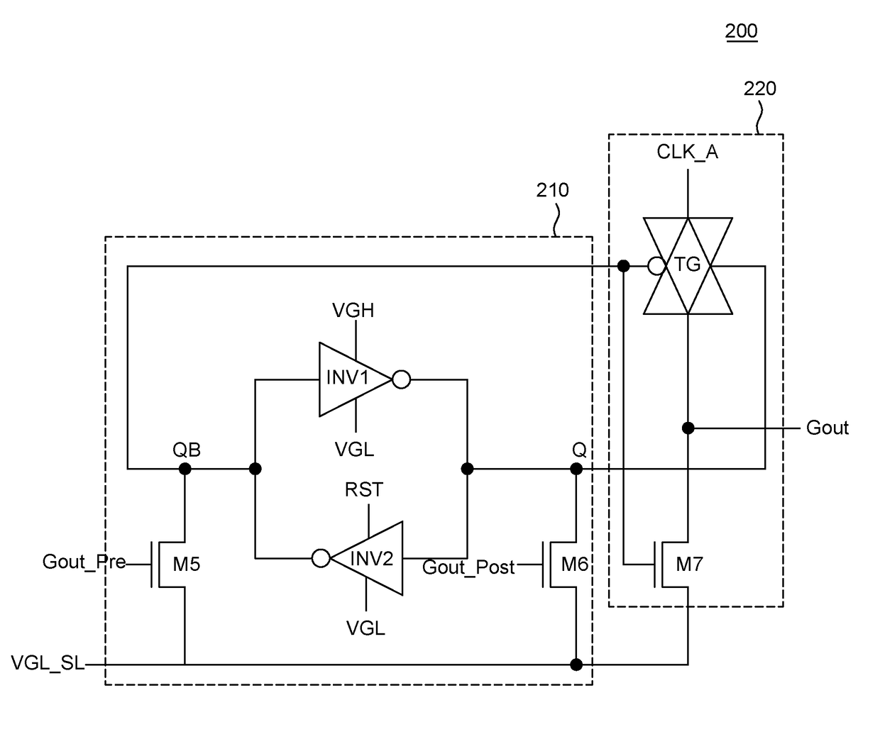
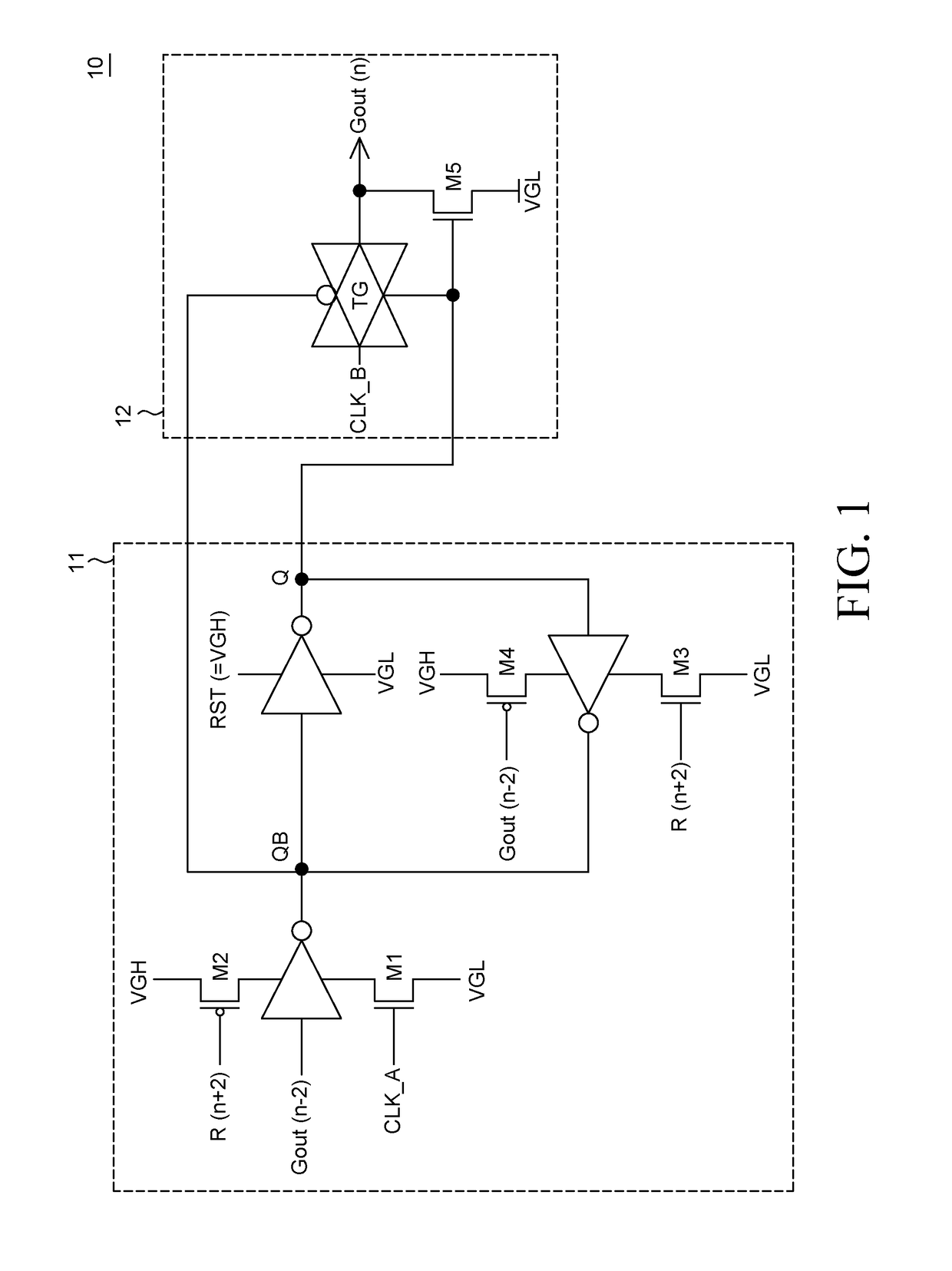
Provided are a GIP driving circuit and a display device using the same. The GIP driving circuit includes: a plurality of stages which sequentially receives a phase-delayed clock and sequentially generates an output. An nth stage (n is a positive integer) includes: a first switch T1 receiving a carry signal from an n−1th stage and controlling a QB node to a low voltage and a Q node to a high voltage when the carry signal has a high voltage; a second switch T2 receiving a carry signal from an n+1th stage and controlling the QB and Q nodes high and low voltages, respectively, when the carry signal has a high voltage; a plurality of inverters connected between nodes Q and QB and constituting a latch; and a buffer outputting a clock as an output voltage when a voltage of the Q node is a high voltage and output.

Description

CROSS-REFERENCE TO RELATED APPLICATIONS[0001]This application claims the priority under 35 U.S.C §119(a) to Republic of Korea Patent Application No. 10-2015-0180775 filed on Dec. 17, 2015, in the Korean Intellectual Property Office, the disclosure of which is incorporated herein by reference.BACKGROUND[0002]Field of Art[0003]The present disclosure relates to a GIP driving circuit including a CMOS (complementary metal-oxide-semiconductor) transistor and a display device using the same.[0004]Description of the Related Art[0005]With the development of the information society, various demands for display devices for displaying image have been increasing. Accordingly, in recent years, various flat panel display (FPD) devices, with lesser weight and volume than a cathode ray tube, have been developed and commercialized. For example, various FPD devices such as a liquid crystal display (LCD), a plasma display panel (PDP), and an organic light emitting diode (OLED) display device are being ...

Claims


Application Information

Patent Timeline
Patent Type & Authority Applications(United States)
IPC IPC(8): G09G3/20
CPCG09G3/2092G09G2310/0243G09G2300/08G09G2310/08G09G3/3266G09G3/344G09G3/3674G09G3/20G11C19/28G09G2310/0267G09G2310/0286G09G2310/0291
Inventor KIM, BYUNGIL
Owner LG DISPLAY CO LTD
Why Eureka
Try Eureka