Composite wheel deburring device

a composite wheel and deburring technology, applied in the field of deburring devices, can solve the problems of increased labour intensity of workers, poor deburring effect of complex wheels, and sharp corners that can be formed very quickly, and achieve the effects of reducing production costs, reducing labor intensity of workers, and simple structur

Active Publication Date: 2017-06-29
CITIC DICASTAL
View PDF7 Cites 17 Cited by
  • Summary
  • Abstract
  • Description
  • Claims
  • Application Information

AI Technical Summary

Benefits of technology

[0011]During actual use, the conveyor belts enable a wheel to reach middle positions of the four V-shaped rollers, the elevating cylinders lift the wheel, and the pneumatic motor drives the screw rod to rotate, so that the left sliding table and the right sliding table drive the four V-shaped rollers to synchronously clamp the wheel, and the driving motor realizes rotation of the wheel under the clamped state; the servo motor I drives the brush I to rotate, and the servo motor II drives the brush II to rotate; the lifting cylinders lift the brushes through the four guide pillars; when the two brushes come in contact with flange rim corner of the wheel, certain pressure is applied, and the brush II starts to remove rim corner burrs at flanges of the wheel; besides, the right servo electric cylinder enables the brush I to move to an appropriate position, and the jacking cylinder enables the brush I to perpendicularly come in contact with window rim corners at roots of the flanges by a guide rail II, so that rim corner burrs at the position can be well removed; an upper servo electric cylinder adjusts the angle of the brush II to an appropriate angle, so that rim corner burrs of wheel rims are removed.
[0012]During use, emphasis treatment can be performed on the rim corner burrs at the roots of the flanges of the wheel with various shapes and the rim corner burrs at the roots of the wheel rims, so that hand burnishing on the burrs at the window is completely replaced, the labor intensity of workers is greatly reduced, and the production cost is reduced; besides, the deburring device has the characteristics of being simple in structure, high in automation degree, advanced in technology, high in generality, high in efficiency and safe and stable in performance.

Problems solved by technology

If sharp corners and burrs on a wheel cannot be well removed, positions where the sharp corners and the burrs are formed can be very quickly corroded when wheels are used, so that appearance effect is directly influenced.
At current, nearly all of wheel manufacturing enterprises adopt special deburring equipment in which an upper circular brush and a lower circular brush are used for deburring a back cavity and a front side; such a manner has an acceptable effect on the wheels with simple front shapes, but has poor deburring effect on the wheels with complicated shapes; some positions which are difficult to debur need hand burnishing, so that not only is the labour intensity of workers increased, the production efficiency is reduced, but also the unit production cost of the wheels is increased.

Method used


Image

  • Composite wheel deburring device
  • Composite wheel deburring device
  • Composite wheel deburring device

Examples


Embodiment Construction

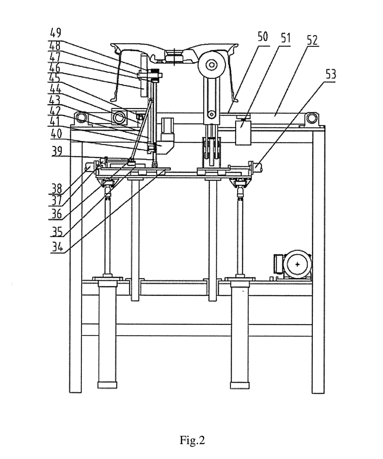
[0017]In the following, the details and working conditions of a specific device provided by the present invention are described in detail in combination with figures.

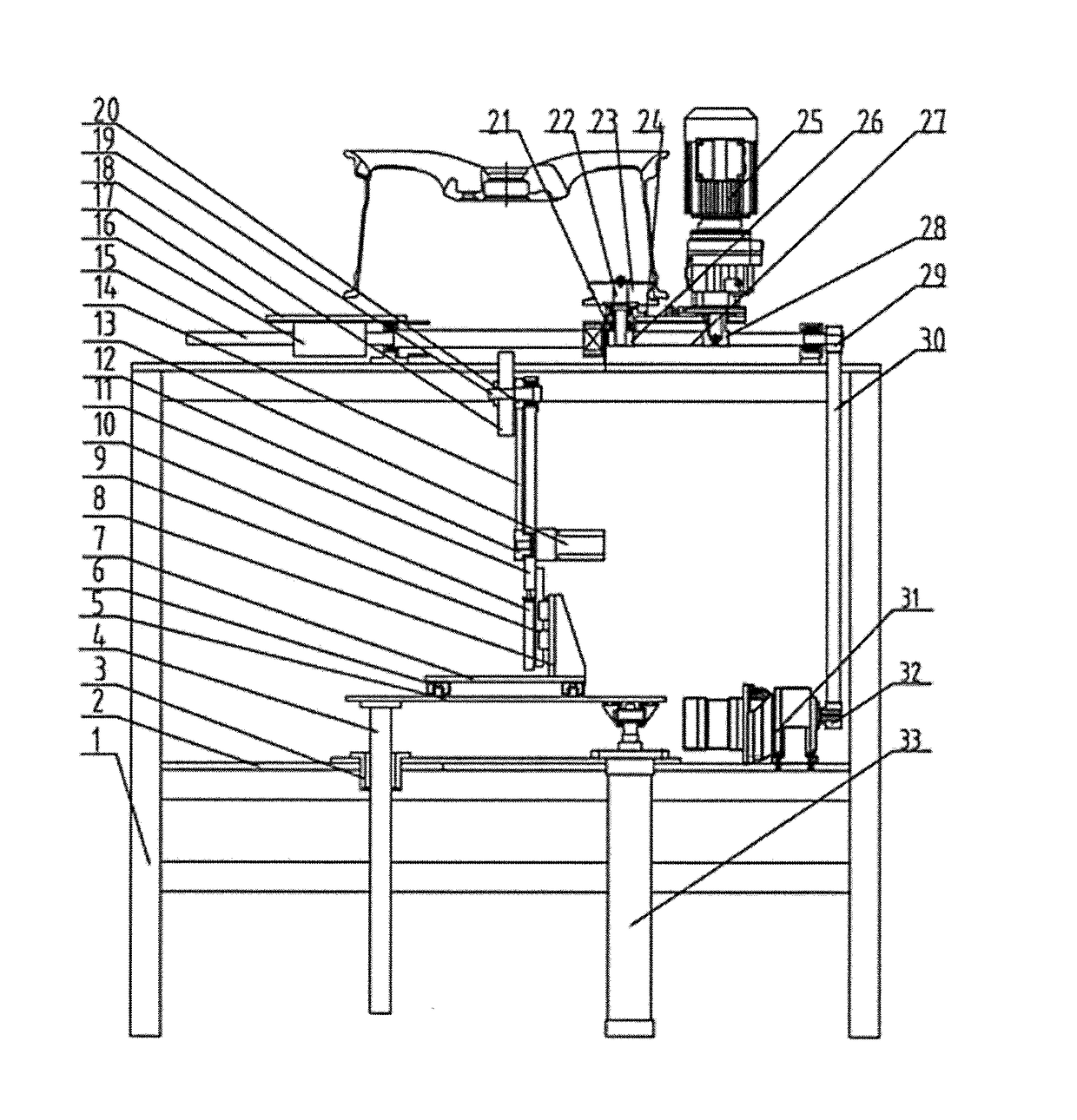
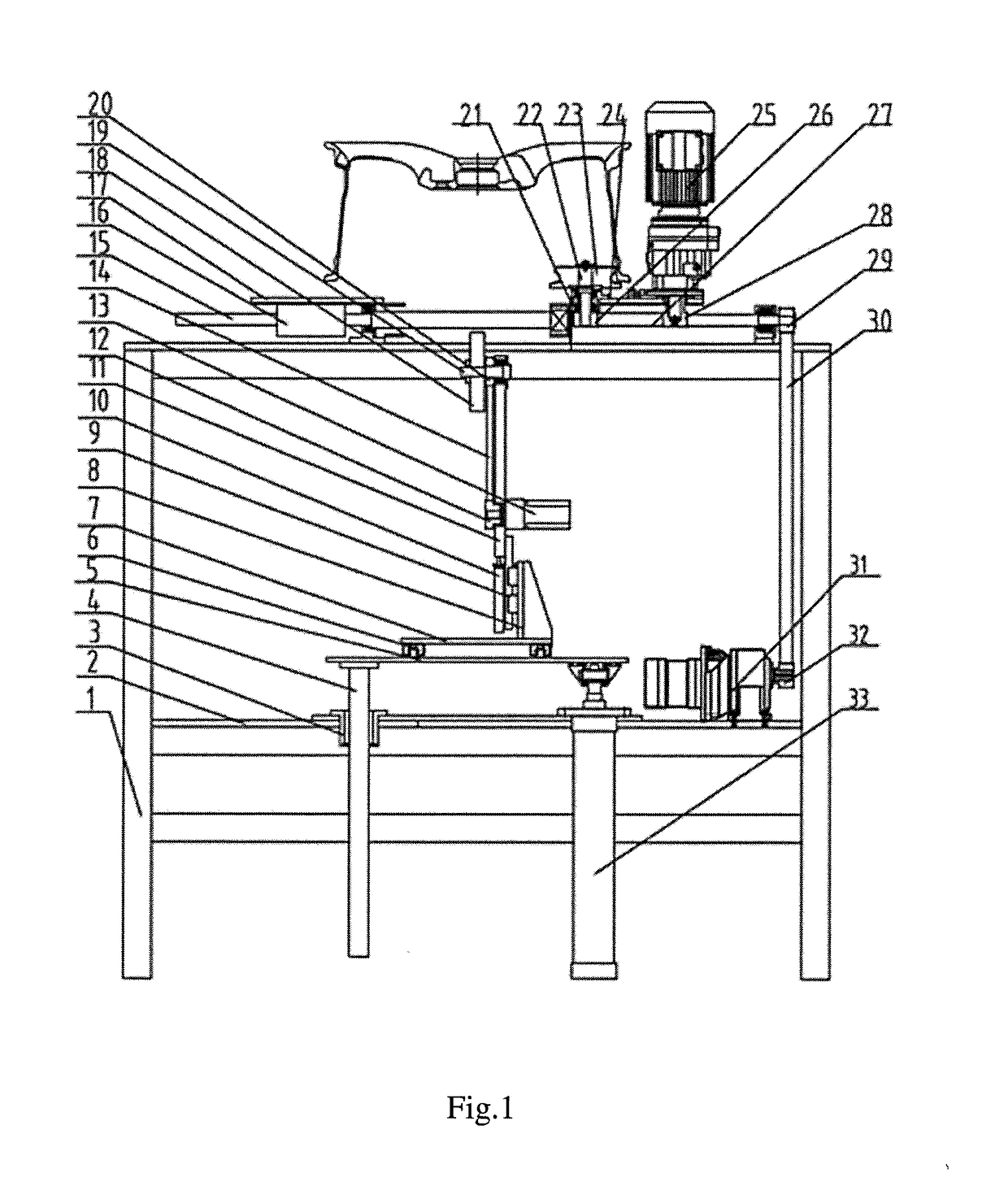
[0018]The composite wheel deburring device comprises a brush system I, a brush system II, and a synchronous clamping rotary system.

[0019]Four guide pillars 4 are fixed under a lifting plate I 5, four guide sleeves 3 matched with the four guide pillars 4 are fixed on a bottom plate 2, and output ends of two lifting cylinders 33 which are also fixed on the bottom plate 2 are hinged to positions under the lifting plate I 5.

[0020]The brush system I comprises a right sliding plate frame 7, an upright plate 8, a guide rail II 9, a jacking cylinder 10, a lifting plate II 11, a belt wheel I 12, a servo motor I 13, a synchronous belt I 14, a screw rod 15, nuts 16, a left sliding table 17, a brush I 18, a shaft I 19, a belt wheel II 20 and a right servo electric cylinder 53, wherein the right sliding plate frame 7 is mounted abov...


PUM


Abstract

The present invention relates to a composite wheel deburring device, which is composed of a stand, servo motors, guide rails, a brush system I, a brush system II, and a synchronous clamping rotary system. During use, emphasis treatment can be performed on the rim corner burrs at the roots of the flanges of the wheel with various shapes and the rim corner burrs at the roots of the wheel rims.

Description

CROSS-REFERENCE TO RELATED APPLICATIONS[0001]This application claims priority to Chinese Patent Application No. 201511006541.6, filed on Dec. 29, 2015, which is hereby incorporated by reference in its entirety.TECHNICAL FIELD[0002]The present invention relates to a deburring device, and in particular to an on-line composite wheel deburring device.BACKGROUND ART[0003]For manufacturing enterprises of aluminum alloy wheels, deburring is an important link after machining procedures. If sharp corners and burrs on a wheel cannot be well removed, positions where the sharp corners and the burrs are formed can be very quickly corroded when wheels are used, so that appearance effect is directly influenced. At current, nearly all of wheel manufacturing enterprises adopt special deburring equipment in which an upper circular brush and a lower circular brush are used for deburring a back cavity and a front side; such a manner has an acceptable effect on the wheels with simple front shapes, but h...

Claims


Application Information

Patent Timeline
Patent Type & Authority Applications(United States)
IPC IPC(8): B24B9/04B24B19/00
CPCB24B19/00B24B9/04B24B27/0076B24B41/02B24B41/06B24B47/00B24B47/12B24B29/005B24B41/005B24B5/44B24B5/12B24B41/00
Inventor XUE, BOWENGUO, JIANDONG
Owner CITIC DICASTAL
Why Eureka
Try Eureka