Gas Separation Process Using Membranes with Permeate Sweep to Remove CO2 from Combustion Exhaust

a gas separation and combustion exhaust technology, applied in separation processes, emission prevention, lighting and heating apparatus, etc., can solve the problems of power plants producing enormous amounts of flue gas, and achieve the effect of less cost and simpler transport of carbon dioxide enriched exhaust gas

Active Publication Date: 2017-06-29
MEMBRANE TECH & RES
View PDF0 Cites 21 Cited by
  • Summary
  • Abstract
  • Description
  • Claims
  • Application Information

AI Technical Summary

Benefits of technology

[0013]The process of the invention involves treating the exhaust or flue gas to remove carbon dioxide. In preferred embodiments, the carbon dioxide level of the exhaust gas is reduced to as low as 5 vol % or less. Discharge of such a stream to the environment is much less damaging than discharge of the untreated exhaust.
[0055]The cost of compression is typically lower when the gas being compressed is cool. Thus, it is preferred that the exhaust stream is cooled prior to being sent to the compression apparatus. Cooling may be performed in any manner, and in one or more sub-steps, including, but not limited to, simple air or water cooling, heat exchange against other on-site process streams, chilling by external refrigerants, cooling in a condensation step, and any combinations of these. Likewise, the energy recovered in the expander unit is higher when the gas being expanded is warm. Warming may be accomplished in any way, preferably by heat exchange against the hot exhaust stream.

Problems solved by technology

In particular, power plants generate enormous amounts of flue gas.

Method used


Image

  • Gas Separation Process Using Membranes with Permeate Sweep to Remove CO2 from Combustion Exhaust
  • Gas Separation Process Using Membranes with Permeate Sweep to Remove CO2 from Combustion Exhaust
  • Gas Separation Process Using Membranes with Permeate Sweep to Remove CO2 from Combustion Exhaust

Examples


example 1

Calculations for Other Examples

[0111](a) Membrane Permeation Experiments:

[0112]The following calculations were performed using a composite membrane having a polyether-based selective layer with the properties shown in Table 1.

TABLE 1GasPermeance (gpu)*CO2 / Gas SelectivityCarbon dioxide1,000  —Nitrogen3033Oxygen6017Hydrogen100 10Water5,000** —*Gas permeation unit; 1 gpu = 1 × 10⁻⁶ cm3(STP) / cm2 · s · cmHg**Estimated, not measured

[0113](b) Calculation Methodology:

[0114]All calculations were performed using a modeling program, ChemCad 5.6 (ChemStations, Inc., Houston, Tex.), containing code for the membrane operation developed by MTR's engineering group. For the calculations, all compressors and vacuum pumps were assumed to be between 75-85% efficient. In each case, the modeling calculation was performed to achieve 90% recovery of carbon dioxide from the flue gas stream, except for Examples 8 and 9.

[0115](c) “No Membrane” Example:

[0116]A computer calculation was performed to determine th...

example 2

n Process with Partial Flue Gas Recycle and No Membrane Step (not in Accordance with the Invention)

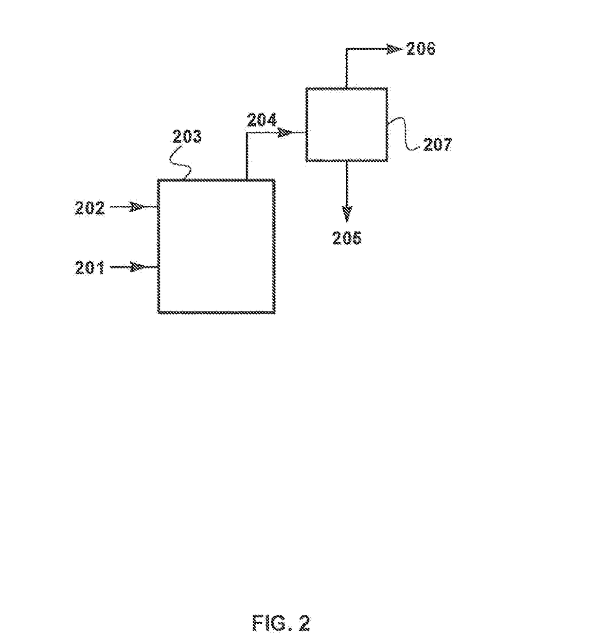
[0120]A computer calculation was performed to determine the chemical composition of untreated exhaust gas from a natural gas combustion process. The process differed from the base-case calculation of Example 1 in that the intake of air was reduced to about half that of Example 1, and the remainder of the gas required for temperature and flow control in the combustor was assumed to be provided by recirculating a portion of the combustion exhaust gas to the combustor inlet, as is commonly done. FIG. 3 is a schematic drawing of a flow scheme for such a combustion process.

[0121]Referring to FIG. 3, natural gas stream 302 and air stream 304 are introduced into combustion step or zone 312. Stream 304 is made up of recycled exhaust stream 307 and additional air or oxygen supply stream 301.

[0122]Combustion exhaust stream 305 is withdrawn, then routed through a condenser 314, where water 310 is...

example 3

f the Invention

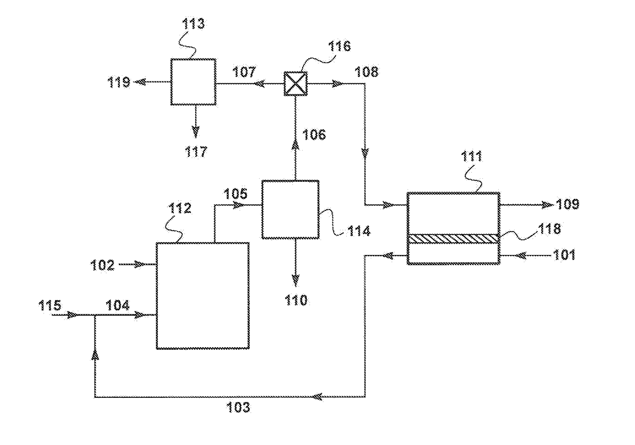
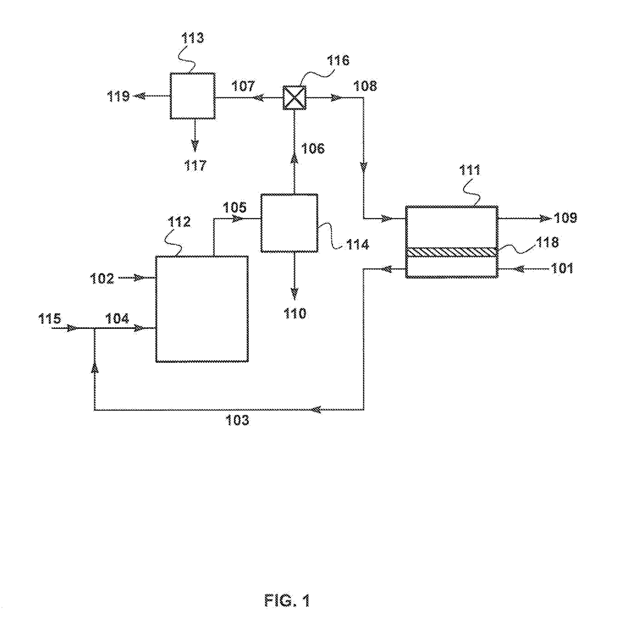
[0125]The calculations for this Example were performed using the flow scheme shown in FIG. 1 and described in the Detailed Description, above. This flow scheme includes a sweep-based membrane separation step 111, which was assumed to be carried out using membranes having the permeation properties listed in Table 1. In this calculation, stream 105 leaving the combustor was at a pressure of 3 bar, which facilitated the operation of the membrane sweep and the carbon dioxide capture step.

[0126]To facilitate operation of the calculation software, for Examples 3 through 7, the base case air flow provided to the combustor via the membrane permeate side was assumed to be about 975 m3 / h (1,250 kg / h), compared with the typical air flow to a 500 MW power plant of about 1.8 million m3 / h used for the calculations of Examples 1 and 2. In other words, the scale of the calculation for the following Examples was about 1 / 1,200 of the scale for a typical natural gas-fired power plant. T...


PUM

PropertyMeasurementUnit
vol %aaaaaaaaaa
vol %aaaaaaaaaa
vol %aaaaaaaaaa

Abstract

A gas separation process for treating exhaust gases from combustion processes. The invention involves routing a first portion of the exhaust stream to a carbon dioxide capture step, while simultaneously flowing a second portion of the exhaust gas stream across the feed side of a membrane, flowing a sweep gas stream, usually air, across the permeate side, then passing the permeate / sweep gas back to the combustor.

Description

CROSS-REFERENCE TO RELATED APPLICATIONS[0001]This application is a continuation-in-part and claims the benefit of U.S. application Ser. No. 15 / 066,771, filed Mar. 10, 2016, which is a divisional of U.S. application Ser. No. 13 / 548,827, filed Jul. 13, 2012, which issued Oct. 4, 2016 as U.S. Pat. No. 9,457,313; which is a continuation-in-part and claims the benefit of both (1) U.S. application Ser. No. 13 / 115,726, filed May 25, 2011, which issued Jul. 17, 2012 as U.S. Pat. No. 8,220,248; which is a continuation-in-part and claims the benefit of U.S. application Ser. No. 13 / 122,136, filed Mar. 31, 2011, which issued May 15, 2012 as U.S. Pat. No. 8,177,885; which is a national stage application of, and claims the benefit of, PCT Application No. PCT / US10 / 02480, filed Sep. 13, 2010; and (2) U.S. application Ser. No. 13 / 122,136, filed Mar. 31, 2011, which issued May 15, 2012 as U.S. Pat. No. 8,177,885; which is a national stage application of, and claims the benefit of, PCT Application No....

Claims


Application Information

Patent Timeline
Patent Type & Authority Applications(United States)
IPC IPC(8): F01N3/08B01D53/14F01N3/02B01D53/22
CPCF01N3/0857B01D53/229B01D53/1475B01D53/1493F01N2570/10B01D2252/20405B01D2252/20421B01D2252/20484F01N3/0205Y02E20/16B01D53/22B01D53/62F01K5/00F02C3/34F02C6/18F23C9/00B01D2256/22B01D2257/102B01D2257/104B01D2257/504B01D2258/0283F05D2260/61F23J2215/50F23L2900/07001F05D2260/611Y02A50/20Y02C20/40Y02E20/32
Inventor BAKER, RICHARD W.MERKEL, TIMOTHY C.WIJMANS, JOHANNES G.
Owner MEMBRANE TECH & RES
Why Eureka
Try Eureka