
Floormat physiological sensor

a sensor and physiological technology, applied in the field of sensors, can solve the problems of nullifying the value of such measurements, affecting treatment, and measurement errors, and achieve the effects of simple form factor, simple use, and compliance of patients

Inactive Publication Date: 2017-07-06
TOSENSE
View PDF17 Cites 2 Cited by
  • Summary
  • Abstract
  • Description
  • Claims
  • Application Information

AI Technical Summary

Benefits of technology

The patent describes a physiological sensor that can be used at home, called the floormat. This device measures various vital signs and hemodynamic parameters, including blood pressure, and helps to monitor patients with heart failure, cardiac arrhythmias, and other diseases. The floormat is easy to use, with a simple form factor that integrates into the patient's daily activities. It includes a pressure-delivery system and an algorithm to estimate blood pressure using both cuff-based and cuffless techniques, allowing for accurate blood pressure readings while minimizing discomfort for patients. The floormat is designed to provide early detection of health risks and support patient compliance with regular use. It improves the repeatability and reproducibility of its measurements, similar to a conventional bathroom scale. Overall, the floormat offers a convenient and effective solution for home monitoring of patient health.

Problems solved by technology

For TFC deviation in the day-to-day placement of the electrodes can result in measurement errors.
This, in turn, can lead to misinformation (particularly when trends of the measured parameters are to be extracted), thereby nullifying the value of such measurements and thus negatively impacting treatment.
Unfortunately, during a measurement, the lead wires can pull on the electrodes if the device is moved relative to the patient's body, or if the patient ambulates and snags the lead wires on surrounding objects.
Such pulling can be uncomfortable or even painful, particularly where the electrodes are attached to hirsute parts of the body, and this can inhibit patient compliance with long-term monitoring.
Moreover, these actions can degrade or even completely eliminate adhesion of the electrodes to the patient's skin, and in some cases completely destroying the electrodes' ability to sense the physiological signals at various electrode locations.
Chronic elevation of LVEDP causes transudation of fluid from the pulmonary veins into the lungs, resulting in shortness of breath (dyspnea), rapid breathing (tachypnea), and fatigue with exertion due to the mismatch of oxygen delivery and oxygen demand throughout the body.
As CO is compromised, the kidneys respond with decreased filtration capability, thus driving retention of sodium and water and leading to an increase in intravascular volume.
However, an extremely delicate balance between these two biological treatment modalities needs to be maintained, since an increase in blood pressure (which relates to afterload) or fluid retention (which relates to preload), or a significant change in heart rate due to a tachyarrhythmia, can lead to decompensated HF.
Unfortunately, this condition is often unresponsive to oral medications.
However, by itself, this parameter is typically not sensitive enough to detect the early onset of CHF—a particularly important stage in the condition when the condition may be ameliorated simply and effectively by a simple change in medication or diet.
As noted above, these organs then respond with a reduction in their filtering capacity, thus causing the patient to retain sodium and water and leading to an increase in intravascular volume.
This, in turn, leads to congestion, which is manifested to some extent by a build-up of fluids in the patient's thoracic cavity (e.g. TFC).
CHF is also the leading cause of mortality for patients with ESRD, and this demographic costs Medicare nearly $90,000 / patient annually.
Less-than-satisfactory consistency with the use of any medical device (in terms of duration and / or methodology) may be particularly likely in an environment such as the patient's home or a nursing home, where direct supervision may be less than optimal.

Method used


Image

  • Floormat physiological sensor
  • Floormat physiological sensor
  • Floormat physiological sensor

Examples


Embodiment Construction

1. Product Overview

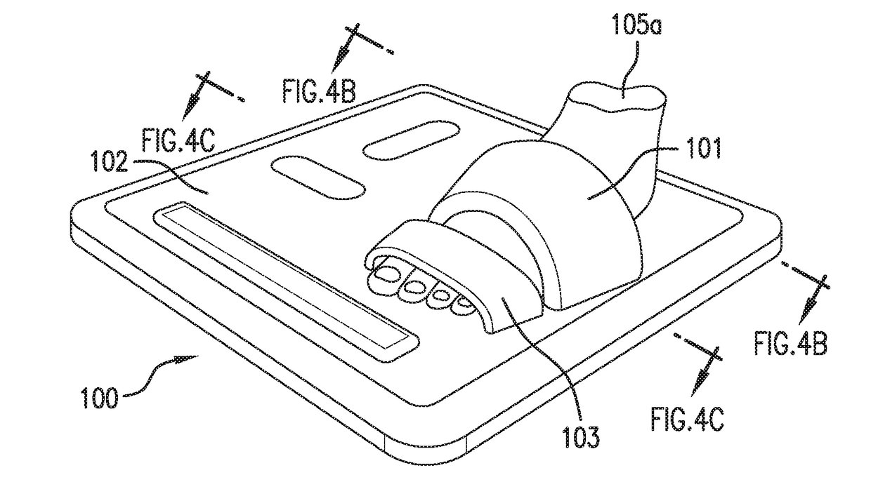
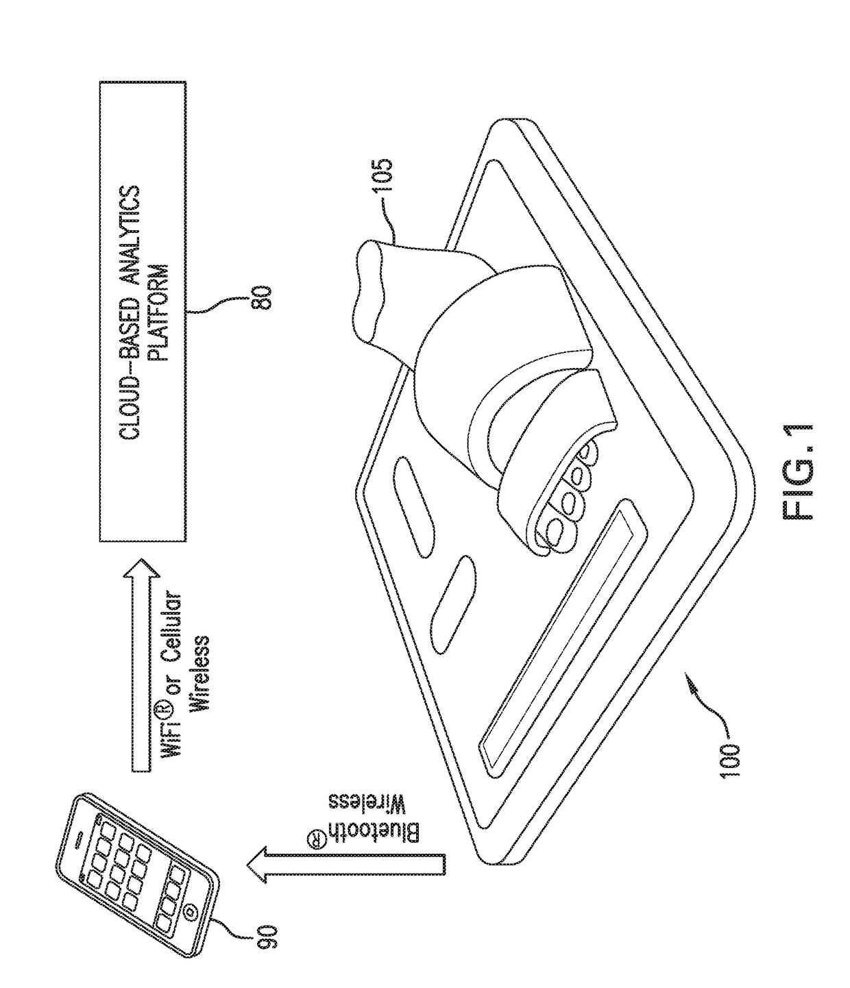
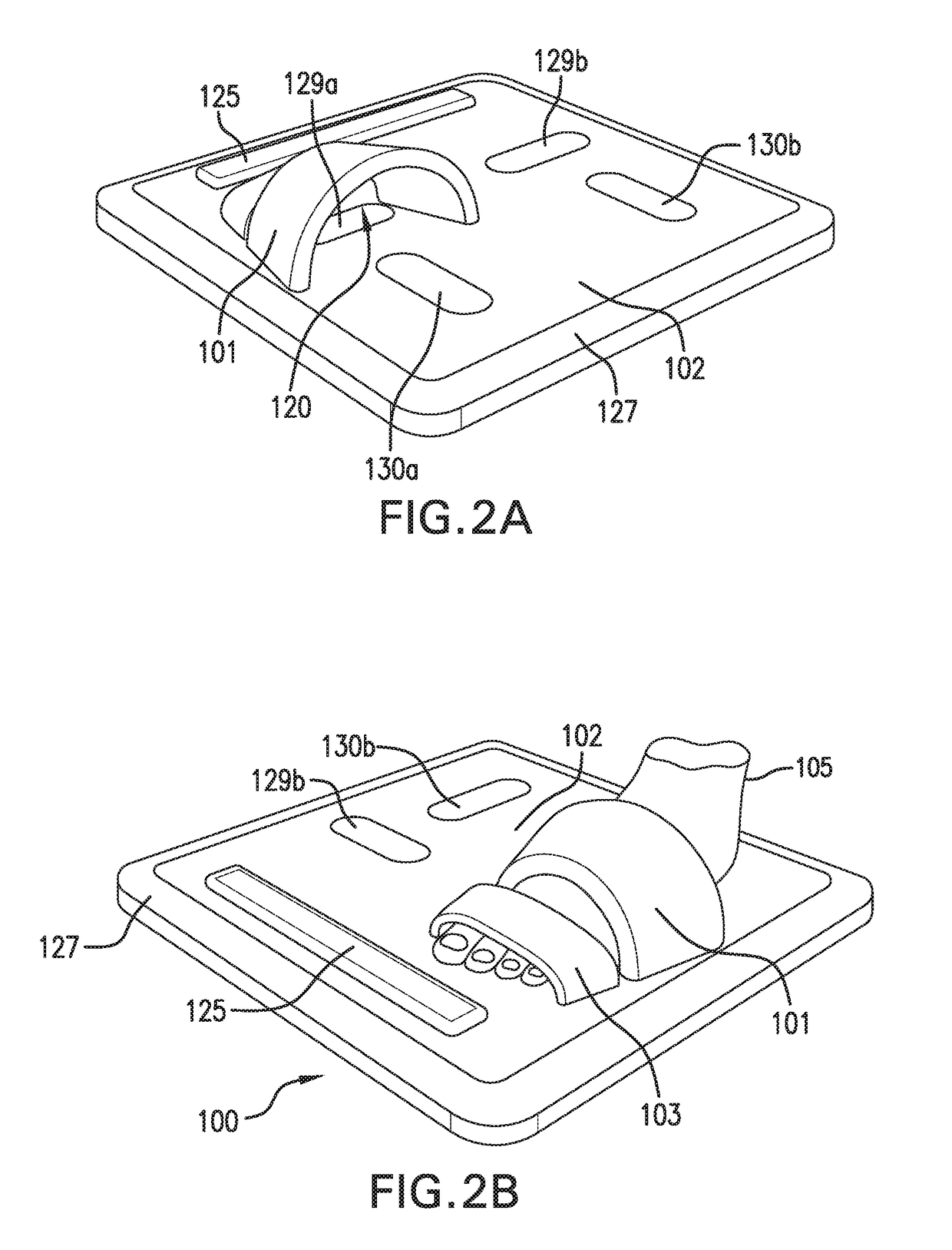
[0105]As shown in FIG. 1, the invention provides a stand-on sensor (“floormat”) 100 that measures a number of physiological parameters, e.g. vital signs (e.g. HR, RR, SpO2, SYS, DIA), hemodynamic parameters (CO, SV, TFI), and biometric parameters (weight, percent body fat, muscle mass) of a patient 105. More specifically, the floormat 100 measures these parameters from the patient's feet, as is described in more detail below. In this way, a comprehensive set of physiological data can be measured easily and on a daily basis while the patient 105 simply stands on the floormat 100, in a manner that is similar to how the patient would use a standard bathroom scale to weigh himself or herself.

[0106]Once the physiological information is obtained, the floormat 100 wireles sly transmits it, e.g., using a short-range wireless technology (suitably Bluetooth® wireless technology) to a mobile device 90, e.g., a conventional smartphone or tablet computer belonging to the patie...


PUM


Abstract

A stand-on physiological sensor (e.g. floormat) measures vital signs and various hemodynamic parameters, including blood pressure and ECG waveforms. The sensor is similar in configuration to a common bathroom scale and includes electrodes that take electrical measurements from a patient's feet to generate bioimpedance waveforms, which are analyzed digitally to extract various other parameters, as well as a cuff-type blood pressure system that takes physical blood pressure measurements at one of the patient's feet. Blood pressure can also be calculated / derived from the bioimpedance waveforms. Measured parameters are transmitted wirelessly to facilitate remote monitoring of the patient for heart failure, chronic heart failure, end-stage renal disease, cardiac arrhythmias, and other degenerative diseases.

Description

BACKGROUND AND FIELD OF THE INVENTION[0001]1. Field of the Invention[0002]The invention relates to sensors that measure physiological signals from patients, and the use of such sensors.[0003]2. General Background[0004]Known electrical or digital weight scales typically use a load cell, integrated into a Wheatstone Bridge circuit, to measure a patient's weight. In such devices, the load cell exhibits a small, force-dependent resistance changes when the patient steps on the scale. The Wheatstone Bridge features four resistors, at least one of which is part of the load cell, and a measurable / ascertainable voltage change across Bridge varies with the force applied to the load cell. The voltage change thus correlates to the patient's weight. Once the scale is calibrated, the voltage is digitized and processed and ultimately converted into a weight, which is then displayed to the patient.[0005]More advanced electrical or digital weight scales include stainless steel electrodes and associa...

Claims


Application Information

Patent Timeline
IPC IPC(8): A61B5/053A61B5/0205G01G19/50A61B5/00
CPCA61B5/0537A61B5/6892A61B5/0535A61B5/6825A61B5/02055A61B5/02405A61B5/021A61B5/0245A61B5/029A61B5/14551G01G19/50A61B5/6829A61B5/0022A61B5/0816A61B5/7225A61B5/7275G16H40/63G16H40/67G16H50/50
Inventor BANET, MATTHEWDHILLON, MARSHAL SINGHPEDE, SUSAN MEEKSHAYWARD, LAUREN NICOLE MILLERDEPTALA, ARTHURCOCHRAN, JONAS DEAN
Owner TOSENSE
Learn More