Anti-fouling system using energy harvested from salt water

a technology of salt water and anti-fouling, which is applied in the direction of lighting applications, instruments, vessel construction, etc., can solve the problems of biofouling creating substantial problems, clogging of water inlets, and machinery stopping working, so as to enhance (human (and/or animal) safety, the effect of reducing light and energy was

Inactive Publication Date: 2017-07-06
KONINKLJIJKE PHILIPS NV
View PDF2 Cites 12 Cited by
  • Summary
  • Abstract
  • Description
  • Claims
  • Application Information

AI Technical Summary

Benefits of technology

[0013]Herein, we propose to harvest the required energy directly from e.g. salt water. Salt water, in combination with two different electrode metals, will generate a current. This current can power a load. On a ship, this principle can be cleverly integrated in already existing cathodic protection solutions: a setup with two different materials; the steel hull is accompanied by a so-called sacrificial anode, e.g. made of zinc. Because of the difference in electrochemical potential, the zinc electrode will corrode rapidly; the steel hull at the same time is protected from corrosion. The power generated by this system is not used for any specific purpose though; it is simply wasted. Cathodic Protection (CP) is a technique used to control the corrosion of a metal surface by making it the cathode of an electrochemical cell. A simple method of protection connects protected metal to a more easily corroded “sacrificial metal” to act as the anode. The sacrificial metal then corrodes instead of the protected metal. With such solution, the source of bio fouling on the fouling surface, which may especially be the liquid which is at least temporarily in contact with the surface, may also be used as source of energy to prevent and / or reduce biofouling on the fouling surface.
[0082]In yet a further embodiment, the object comprises a plurality of lighting modules arranged over at least part of a height of the object, wherein the control system is configured to control an intensity of the anti-fouling light as function of a position of the lighting module relative to a electrically conductive aqueous liquid level of the electrically conductive aqueous liquid at a side of the fouling surface. Especially, the height of the object is defined as the height of the object in use, in e.g. water, from the lowest point below the liquid level to the highest point of the object. Height of elements of such object are defined with the height defined relative to a vertical direction from the lowest point to the highest point. For instance, the height of a hull may be the height from the keel to the e.g. the railing. Advantageously, undesired anti-fouling light above the water level may be reduced (and waste of light and energy may be reduced), whereas below the water level the anti-fouling light may be provided. This also enhances (human (and / or animal) safety, as exposure from e.g. human beings to UV radiation is desirably as low as possible. Hence, the control system may be configured to control an intensity of the anti-fouling light as function of a position of the lighting module relative to the depth of the lighting module below the electrically conductive aqueous liquid level of the electrically conductive aqueous liquid (at a side of the fouling surface).

Problems solved by technology

In several circumstances biofouling creates substantial problems.
Machinery stops working, water inlets get clogged, and hulls of ships suffer from increased drag.
Biofouling on the hull of ships causes a severe increase in drag, and thus increased fuel consumption.
It appears that most micro-organisms are killed, rendered inactive or unable to reproduce with sufficient UV light.
One of the issues / challenges is to provide the electrical power to the system that provides the (UV) light or anti-fouling light; since this is on the outside of the object, such as vessel with a (very large) hull, complications may arise, such as:Drilling holes for the wiring, from the power generator inside the boat, to the system on the outside;The length of cables, running from the power source to the actual LEDs;Any UV LED system will likely have some form of tiling to cover as much as ˜10,000 m2 (or even up to 40,000 for the largest boats around.
The interconnections between individual tiles may be difficult to make;Both a positive and negative electrode are needed, which requires precautions to prevent electrical shorts; especially in salt water, or when damages occur.

Method used


Image

  • Anti-fouling system using energy harvested from salt water
  • Anti-fouling system using energy harvested from salt water
  • Anti-fouling system using energy harvested from salt water

Examples


Embodiment Construction

[0101]While the disclosure has been illustrated and described in detail in the drawings and foregoing description, such illustration and description are to be considered illustrative or exemplary and not restrictive; the disclosure is not limited to the disclosed embodiments.

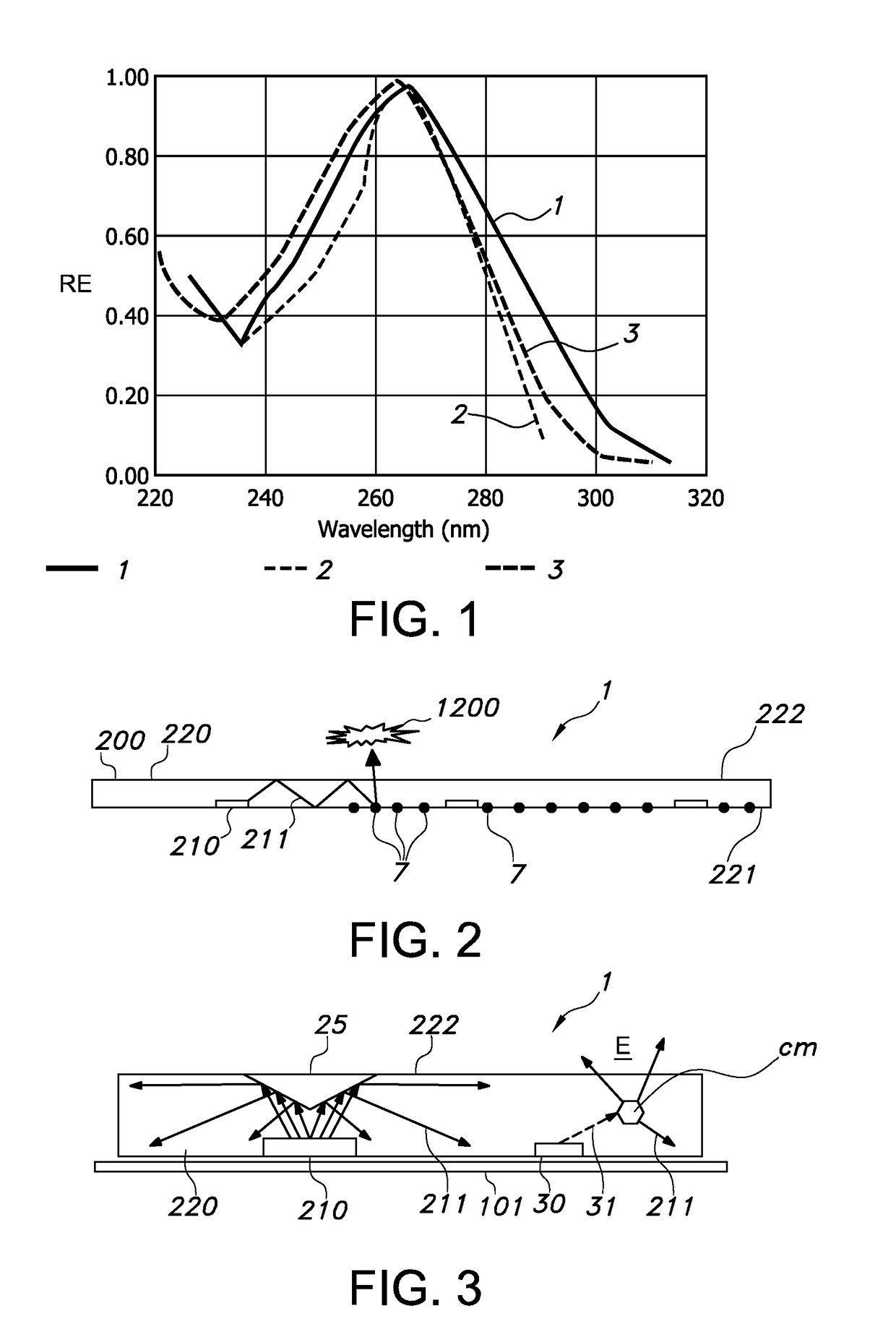
[0102]FIG. 1 is a graph showing a germicidal action spectrum for different biological materials as a function of light wavelength, with RE indicating the relative effectiveness, with curve 1 indicating the germicidal action as derived from the IES Lighting Handbook, Application Volume, 1987, 14-19; curve 2 indicating E. Coli light absorption (as derived from W. Harm, Biological Effects of ultraviolet radiation, Cambridge University Press, 1980), and curve 3 indicating DNA absorption (as also derived from the IES handbook).

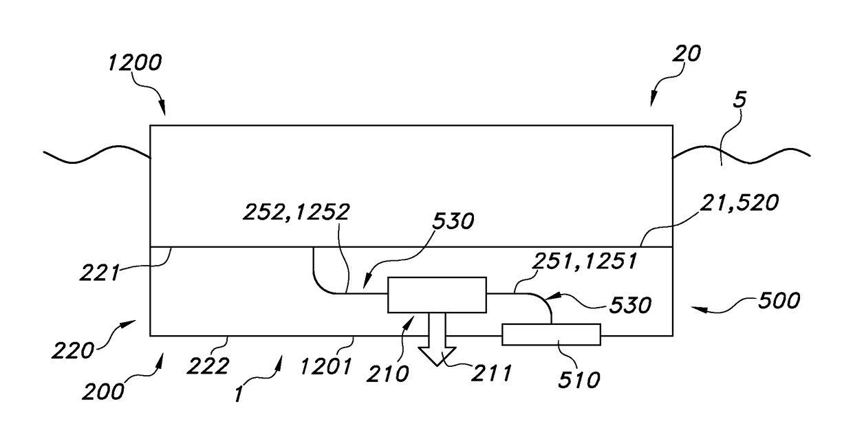
[0103]FIG. 2 shows as a basic embodiment a cross section of a lighting module 200 comprising a plurality of light sources 210 (here: side-emitting LEDs, wherein the light is emitted primarily f...


PUM

PropertyMeasurementUnit
distancesaaaaaaaaaa
wavelengthaaaaaaaaaa
radiation wavelengthsaaaaaaaaaa

Abstract

The invention provides an anti-fouling lighting system (1) configured for preventing or reducing biofouling on a fouling surface (1201) of an object (1200) that during use is at least temporarily exposed to a liquid, by providing an anti-fouling light (211) to said fouling surface (1201), the anti-fouling lighting system (1) comprising: —a lighting module (200) comprising a light source (210) configured to generate an anti-fouling light (211); and —an energy system (500) configured to locally harvest energy and configured to provide electrical power to said light lighting module (200), wherein the energy system (500) comprises (i) a sacrificial electrode (510), and (ii) a second energy system electrode (520), wherein the energy system (500) is configured to provide electrical power to the lighting module (200) when the sacrificial electrode (510) and the second energy system electrode (520) are in electrical contact with the liquid.

Description

FIELD OF THE INVENTION[0001]The invention relates to an anti-fouling lighting system and to an object, such as a vessel or movable construction for use in especially water, comprising such anti-fouling lighting system. The invention further relates to a method of anti-fouling a fouling surface (of such object). Further, the invention relates to a method of providing an anti-fouling lighting system to an object.BACKGROUND OF THE INVENTION[0002]Anti-biofouling methods are known in the art. US2013 / 0048877, for instance, describes a system for anti-bio fouling a protected surface, comprising an ultraviolet light source configured to generate ultraviolet light; and an optical medium disposed proximate to the protected surface and coupled to receive the ultraviolet light, wherein the optical medium has a thickness direction perpendicular to the protected surface, wherein two orthogonal directions of the optical medium orthogonal to the thickness direction are parallel to the protected sur...

Claims


Application Information

Patent Timeline
Patent Type & Authority Applications(United States)
IPC IPC(8): B63B59/04G02B6/10B63B59/08C02F1/32B01J19/12B08B17/02
CPCB01J19/123B08B17/02B63B59/08B63B59/04G02B6/102B63B59/06C02F1/325G02B6/0043B63B2209/04C02F2201/001C02F2103/08C02F2303/20Y02T70/00F21V9/40F21V23/003B63B79/40F21Y2115/10F21W2111/04F21W2107/20
Inventor SALTERS, BART ANDRESEMPEL, ADRIANUS
Owner KONINKLJIJKE PHILIPS NV
Why Eureka
Try Eureka