
Power converter

a power converter and converter technology, applied in the field of power converter packaging and component arrangement, can solve problems such as high inductance and other problems, and achieve the effect of reducing the distance between the capacitor bank

Active Publication Date: 2017-07-06
ATSE LLC
View PDF3 Cites 26 Cited by
  • Summary
  • Abstract
  • Description
  • Claims
  • Application Information

AI Technical Summary

Benefits of technology

The patent describes a power inverter that can convert DC power to AC power. It includes a bank of capacitors that store energy for the inverter to use. The inverter also has a driver module that controls the switching of the modules to produce the AC output. The driver module has planar transformers that help reduce the distance between the capacitor bank and the driver module. This design helps improve the efficiency and performance of the power inverter.

Problems solved by technology

Issues related to high inductance may occur between components of a conventional power converter.

Method used


Image

  • Power converter
  • Power converter
  • Power converter

Examples


Embodiment Construction

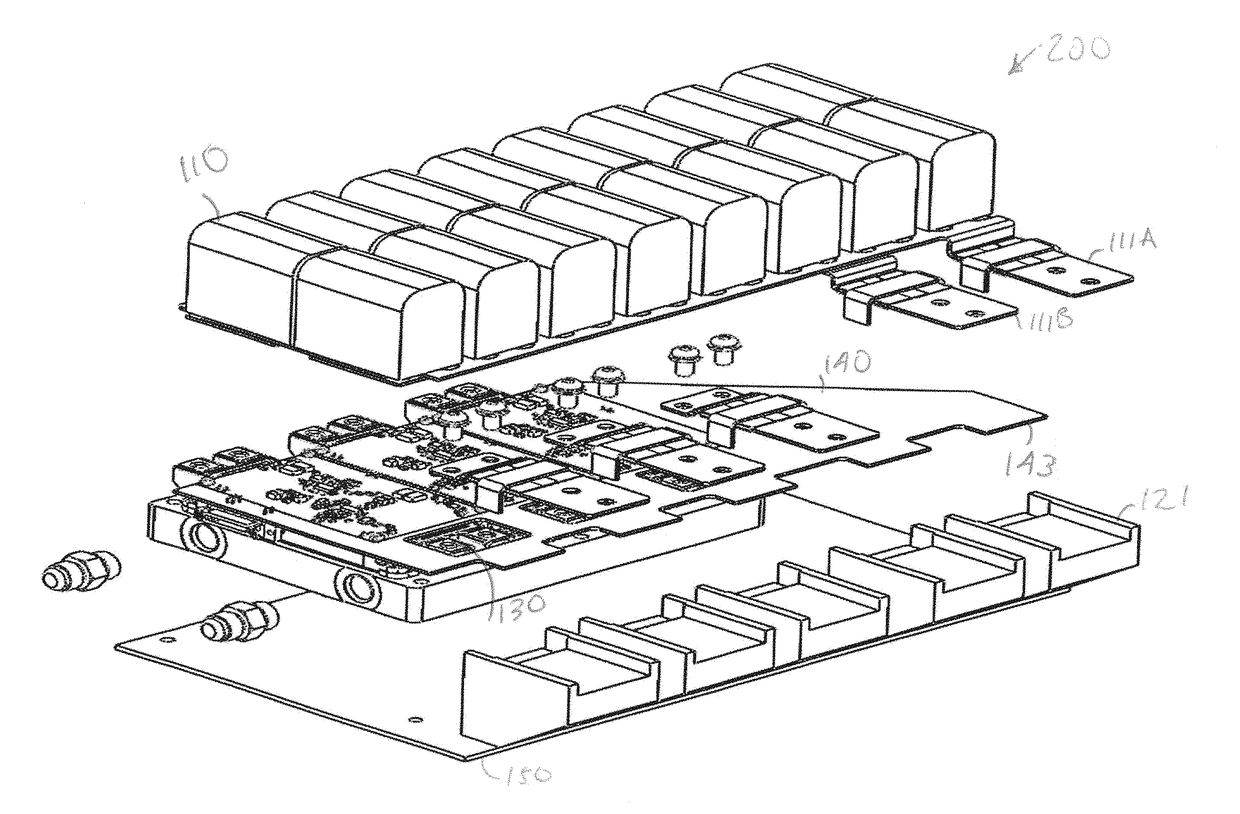
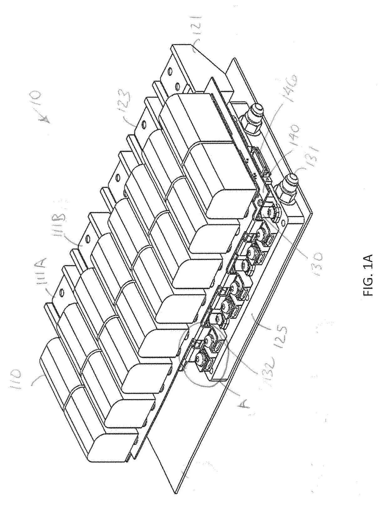
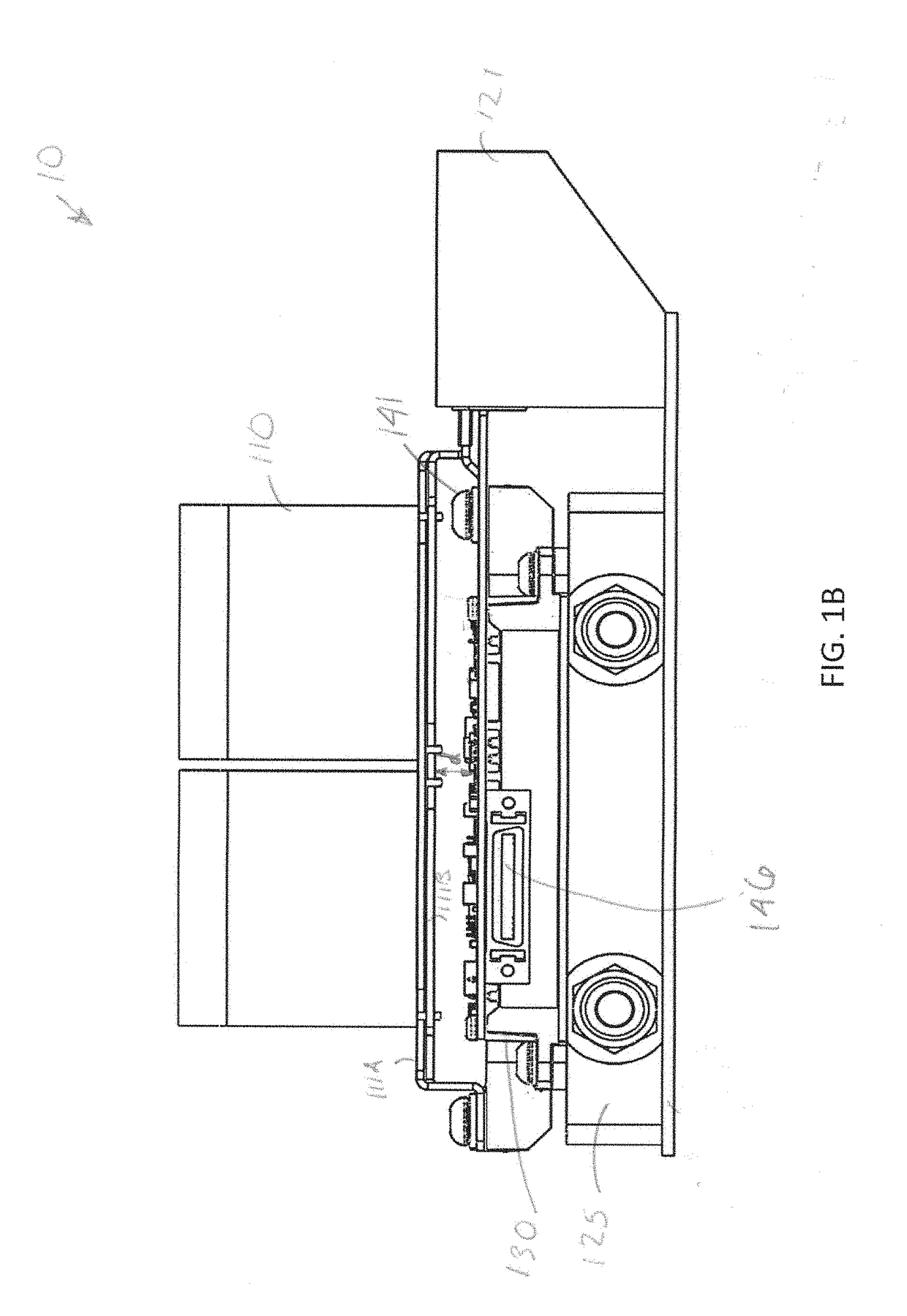
[0038]FIG. 1A is an isometric view of a power converter 10, in accordance with some embodiments. FIG. 1B is a front view of the converter 10 of FIG. 1A. FIG. 1C is a side view of the converter 10 of FIGS. 1A and 1B. FIG. 1D is a top view of the converter 10 of FIGS. 1A-1C. FIG. 1E is an exploded front view of the converter 10 of FIGS. 1A-1D. FIG. 1F is an exploded side view of the converter 10 of FIGS. 1A-1E. FIGS. 2-5 are views of various elements of the converter 10. FIGS. 6A-6E, 7, and 8A-8G are views of assemblies of various elements of the converter 10.

[0039]The converter 10 can convert a DC input into AC, which may be output from the converter 10 via terminals 123 positioned in terminal blocks 121. In other embodiments, the converter 10 may convert an AC input into DC. In other embodiments, the converter 10 may convert a DC input into DC. Thus, terminals 123 may be AC output terminals in an inverter mode (DC / AC), AC inputs in a rectifier mode (AC / DC), or DC outputs for a DC / DC...


PUM


Abstract

A power inverter comprises a plurality of high power switching modules that form an alternating current (AC) output; a plurality of terminals in communication with the high power switching modules for outputting the AC output; a capacitor bank that provides a conditioned voltage to the high power switching modules for producing the AC output in response to receiving and storing electrical energy related to a direct current (DC) supply; and a case positioned over the high power switching modules. The capacitor bank is mounted to the case, and the capacitor bank is positioned over the high power switching modules so that the high power switching terminals are proximal the capacitor bank for reducing inductance. A gate driver module at a top region of the high power switching modules includes a plurality of planar transformers for reducing a distance between the capacitor bank and the gate driver.

Description

FIELD[0001]The present concepts relate generally to power converter, and more specifically, to packaging and component arrangements for a power converter.BACKGROUND[0002]Power inverters are well-known for receiving electrical power from a generator or other power source, and conditioning the electrical power such as converting the received power from direct current (DC) to alternating current (AC), AC to DC, or DC to DC at a different voltage. Issues related to high inductance may occur between components of a conventional power converter.BRIEF SUMMARY[0003]In one aspect, provided is a power inverter, comprising: a plurality of high power switching modules that form an alternating current (AC) output; a plurality of terminals in communication with the high power switching modules for outputting the AC output; a capacitor bank that provides a conditioned voltage to the high power switching modules for producing the AC output in response to receiving and storing electrical energy rela...

Claims


Application Information

Patent Timeline
IPC IPC(8): H02M7/537H02M7/217H02M3/158
CPCH02M7/537H02M7/217H02M3/158H02M7/003H05K7/20927
Inventor JONES, FRANKLIN B.NEHRING, ANDREW I.JONES, DANIEL T.HUMMEL, ROBERT A.DONAHUE, ERIC D.
Owner ATSE LLC
Learn More