Cooling of aerospace flight systems

a cooling system and aerospace technology, applied in the field of high efficiency cooling system, can solve the problems of high-performance equipment, supersonic or hypersonic aircraft, reusable spacecraft, etc., and achieve the effect of reducing the tendency of being detected and reducing the output of thermal signatures

Inactive Publication Date: 2017-07-13
IOWA STATE UNIV RES FOUND
View PDF2 Cites 9 Cited by
  • Summary
  • Abstract
  • Description
  • Claims
  • Application Information

AI Technical Summary

Benefits of technology

[0007]The present invention provides a new and unique system, for cooling flight systems and flight surfaces of aerospace vehicles. The invention can be applied to a variety of flight systems such as electronics, sensors, lasers, RADAR, propulsion components such as inlets, combustors, and nozzles, thereby providing operational benefits. For example, cooling the nozzle regions of an aircraft reduce their thermal signature output, thereby reducing their tendency of being detected.

Problems solved by technology

Today's high performance aircraft are extremely complex vehicles, due in part to their significant onboard electrical and computer equipment.
In addition, other advanced, high performance equipment, such as supersonic or hypersonic aircraft or reusable spacecraft, are subjected to extremely high operating surface temperatures due to the friction they encounter when traveling through the atmosphere at high rates of speed.
While this form of thermal insulation provided adequate protection for the orbiter vehicle, this system required uniquely designed and costly insulated ceramic tiles positioned along the exposed surfaces of the orbiter, including the leading edge of the wing and nose areas.

Method used


Image

  • Cooling of aerospace flight systems
  • Cooling of aerospace flight systems
  • Cooling of aerospace flight systems

Examples


Embodiment Construction

[0025]The present invention provides systems and methods for improving the cooling of an advanced aerospace vehicle that operates at high speeds and with high surface temperatures. Aspects of the present invention are depicted with respect to FIGS. 1-11.

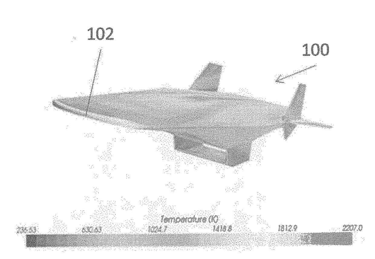
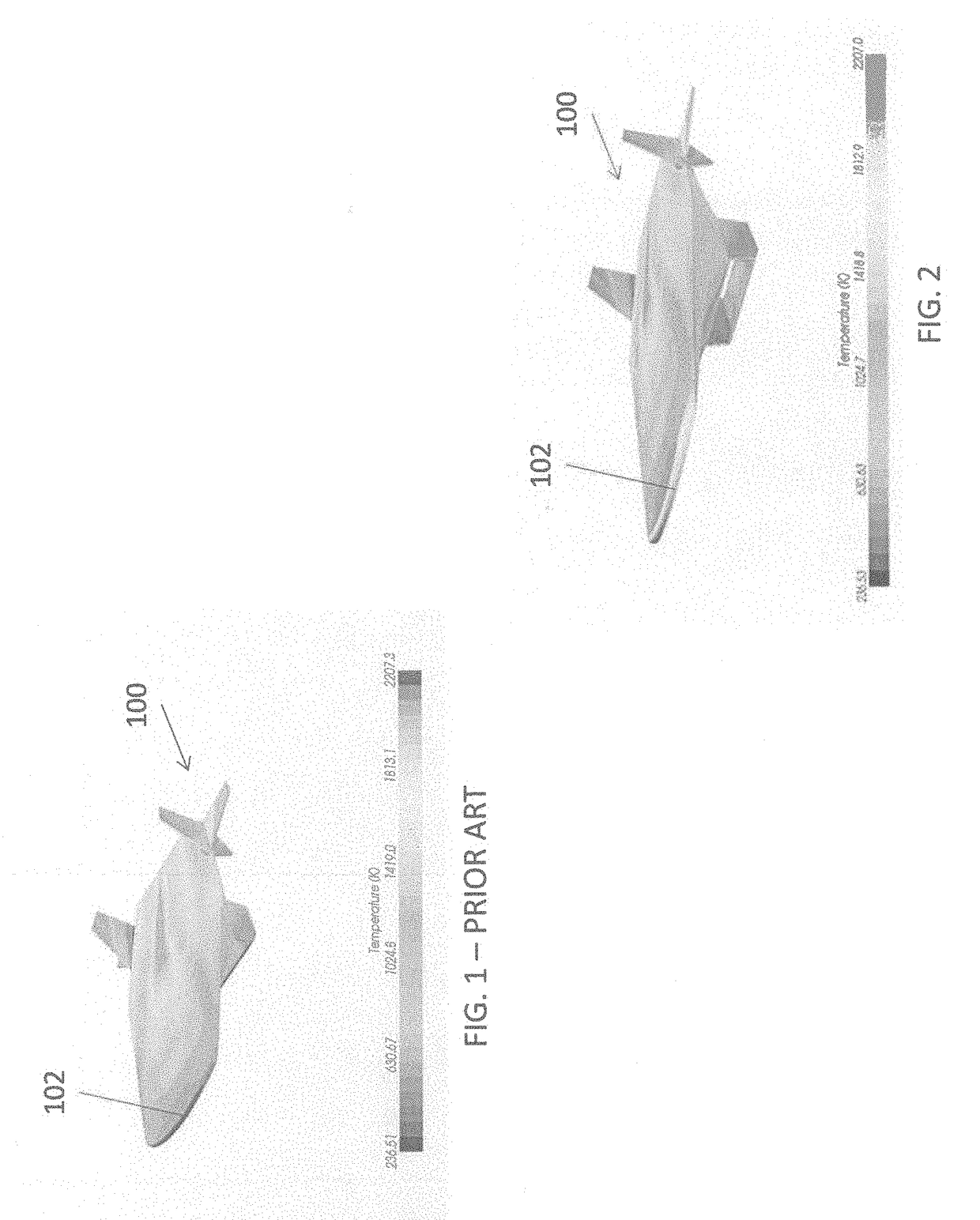
[0026]Referring initially to FIG. 1, an aerospace vehicle 100, in accordance with the prior art, is depicted in perspective view. The vehicle 100 represents a class of high speed aircraft operating at high altitudes and subject to high temperatures due to the friction of air passing over the various surfaces of the vehicle. These high aerodynamic heating rates typically occur on critical flight surfaces such as the nose, wing leading edge, leading edges of the tail or elevator, and proximate engine inlets and nozzles. Representative aerospace vehicles include, but are not limited to, hypersonic aircraft. For the vehicle 100 depicted in FIG. 1, traveling at an altitude of 100,000 feet (approximately 19 miles) and a speed of Mach 7, th...


PUM


Abstract

The invention relates generally to a novel cooling system and fuel preheating system for use in an advanced, high speed aerospace vehicle. A hydrocarbon fluid, such as fuel is accelerated to supersonic conditions within a cooling channel located proximate a high-temperature flight surface. The hydrocarbon fuel absorbs a heat load as it passes through the cooling channel in the flight control surface prior to the fuel being directed into the aircraft engine.

Description

CROSS-REFERENCE TO RELATED APPLICATIONS[0001]This application claims priority to U.S. Provisional Patent Application Ser. No. 62 / 169,690, filed on Jun. 2, 2015.STATEMENT REGARDING FEDERALLY SPONSORED RESEARCH OR DEVELOPMENT[0002]Not applicable.TECHNICAL FIELD[0003]The invention relates generally to a high efficiency cooling system for aerospace flight systems and flight surfaces such as a high speed vehicle where the surface cooling system also provides fuel pre-heating.BACKGROUND OF THE INVENTION[0004]Today's high performance aircraft are extremely complex vehicles, due in part to their significant onboard electrical and computer equipment. This equipment, such as the F-22 and F-35 fighter jets, generate heat that must be dissipated. Due to the heat produced by their advanced avionics systems, these aircraft use a refrigerated fuel to provide sufficient cooling to the onboard electronics.[0005]In addition, other advanced, high performance equipment, such as supersonic or hypersonic...

Claims


Application Information

Patent Timeline
Patent Type & Authority Applications(United States)
IPC IPC(8): B64C3/36B64D37/34B64C1/38B64D37/10B64D37/30F02K7/10B64C3/34
CPCB64C3/36F02K7/10B64D37/34B64C1/38B64D37/10B64D37/30B64C3/34B64G1/58F02C7/224
Inventor GIELDA, THOMAS P.VOGEL, PATRICK G.
Owner IOWA STATE UNIV RES FOUND
Why Eureka
Try Eureka