
Three-dimensional image capturing apparatus and image capturing method using digital holography

a three-dimensional image and image capturing technology, applied in the field of three-dimensional image capturing apparatus using digital holography, can solve the problems of complex system, unsatisfactory configuration, and difficulty in solving the number of photographing times, and achieve the effect of simple configuration and high accuracy of three-dimensional data

Inactive Publication Date: 2017-07-13
CANON KK
View PDF0 Cites 6 Cited by
  • Summary
  • Abstract
  • Description
  • Claims
  • Application Information

AI Technical Summary

Benefits of technology

The present invention is an image capturing device and method that can take highly accurate three-dimensional data with a simple set-up and minimal number of photos.

Problems solved by technology

However, in order to solve a common problem that increases the number of photographing pixels to widen a photographing area, the number of photographing times is a problem to be solved.
If a configuration where a plurality of object light beams are incident is adopted so as to reduce the number of photographing times, the object light beams interfere with each other and accordingly the configuration does not work simply.
However, the wavelength multiplexing needs light sources whose number corresponds to the number of images for overlap photographing, and thus a system is complicated.
Although it is possible to avoid the interference of the object light beams by polarization multiplexing, the polarization multiplexing only has two degrees of freedom at most for the polarization up, and accordingly there is the upper limit for the multiplexing.
In addition, it is necessary to prepare an element for controlling the polarization of each object light beam, add a polarizer to a sensor, and prepare two sensors, and thus the system is complicated.

Method used


Image

  • Three-dimensional image capturing apparatus and image capturing method using digital holography
  • Three-dimensional image capturing apparatus and image capturing method using digital holography
  • Three-dimensional image capturing apparatus and image capturing method using digital holography

Examples


embodiment 1

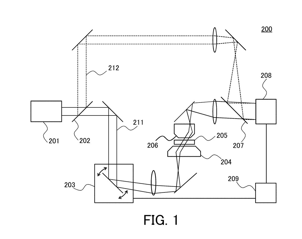
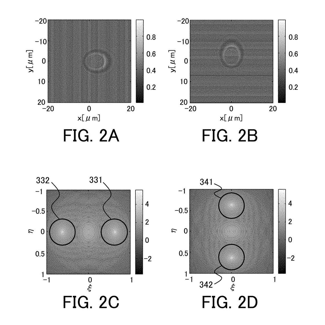
[0056]Next, Embodiment 1 of the present invention will be described. In this embodiment, as an example of a configuration that controls a position of crosstalk occurring due to interference of a plurality of object light beams, a configuration that controls a position of a spectrum of the crosstalk to be located at a position different from a position of a real image spectrum of each of the plurality of object light beams will be described. Specifically, a configuration that controls the spectrum of the crosstalk to be kept away from the vicinity of the center of a frequency space where the real image spectrum exists will be described.

[0057]In order to keep the spectrum of the crosstalk away from the vicinity of the center of the frequency space where the real image spectrum exists, an angle between a position vector of the real image spectrum of an object light beam and an inverse vector of a position vector of the real image spectrum of another object light beam only needs to be s...

embodiment 2

[0070]Next, Embodiment 2 of the present invention will be described. In this embodiment, as an example of a configuration that controls a position of crosstalk occurring due to interference of a plurality of object light beams, a configuration that controls spectra of crosstalks to be collected into a predetermined region (partial region in a frequency space) will be described.

[0071]In order to collect the spectra of the crosstalks in the partial region of the frequency space, an angle between a position vector of a real image spectrum of an object light beam and an inverse vector of a position vector of a real image spectrum of another object light beam only has to be large. In order to achieve this, an angle of a plurality of object light beams may be small, and an azimuth angle φ may be within a certain range.

[0072]Referring to FIG. 7, the range of the azimuth angle φ will be described. FIG. 7 illustrates a position 701 of the real image spectrum of the first object light beam, a...

embodiment 3

[0088]Next, Embodiment 3 of the present invention will be described. While Embodiment 2 describes the configuration of the image capturing apparatus using the plurality of object light beams with a single wavelength, this embodiment can acquire a number of wavefronts at the same time by overlap photography (overlap tomography) of the hologram by using the plurality of object light beams with different wavelengths or with different polarizations.

[0089]In this embodiment, the plurality of object light beams include a plurality of object light beams with different wavelengths from each other which are split from a plurality of light beams emitted from a plurality of light sources (first light source and second light source). The controller controls the plurality of object light beams with different wavelengths so as not to interfere with each other. In this embodiment, a case where overlap photography (overlap tomography) is performed on holograms by using a light source with light sou...


PUM


Abstract

An image capturing apparatus (500) capable of performing three-dimensional tomography of an object by digital holography, includes a splitting element (502) which splits a light beam emitted from a light source into an object light beam and a reference light beam, an illumination system (503) which controls a plurality of object light beams that are generated from the object light beam and that move in directions different from each other to be incident on the object simultaneously, a composite element (507) which causes the plurality of object light beams to interfere with the reference light beam, an image sensor (508) which acquires hologram generated by interference of each of the plurality of light beams with the reference light beam, and a controller (509) which controls the illumination system so that the plurality of object light beams interfere with each other on the image sensor.

Description

BACKGROUND OF THE INVENTION[0001]Field of the Invention[0002]The present invention relates to a three-dimensional image capturing apparatus using digital holography.[0003]Description of the Related Art[0004]Previously, as one of methods of measuring a distribution of a transparent object, mainly a refractive index distribution, digital holography is known. Here, a basic technology of the digital holography will be described. First, an incident light beam emitted from a light source such as a laser with high coherency is separated into an object light beam and a reference light beam by using a beam splitter or the like. Next, a specimen is disposed on the object light beam so that only the object light beam passes through the specimen. Then, the object light beam and the reference light beam are combined, i.e., interfere with each other, by using the beam splitter or the like, and an interference fringe that is generated by interference between the object light beam and the reference...

Claims


Application Information

Patent Timeline
IPC IPC(8): G03H1/04
CPCG03H1/0443G03H2001/0452G03H2001/0445G03H2001/0473G03H2223/24G03H2001/045G03H2210/30G03H2223/12G03H2222/20G03H1/0866G03H1/265G03H2001/046G03H1/0465G03H2001/0456
Inventor MATSUBARA, ISAOEGUCHI, AKIRA
Owner CANON KK
Learn More