Optical device and image projection apparatus including the same

a technology of optical devices and projection apparatuses, applied in the direction of picture reproducers, polarising elements, instruments using projection devices, etc., can solve the problems of difficult to provide compact optical devices, achieve high light output, improve the reliability of polarization converters, and high efficiency of light outpu

Active Publication Date: 2017-07-13
LG ELECTRONICS INC
View PDF2 Cites 4 Cited by
  • Summary
  • Abstract
  • Description
  • Claims
  • Application Information

AI Technical Summary

Benefits of technology

[0009]An optical device according to an embodiment of the present invention and an image projection apparatus including the same each include a laser diode for outputting a laser light having a predetermined wavelength, a polarization separator for transmitting a first polarized light of the laser light and reflecting a second polarized light of the laser light, a wheel including a wavelength conversion unit for converting a wavelength of the second polarized light of the laser light reflected by the polarization separator such that the second polarized light of the laser light corresponds to one selected from among a blue light, a green light, and a red light and a transmission unit for transmitting the other lights, a polarization converter for converting the light transmitted through the wheel into the first polarized light and outputting the converted first polarized light to the wheel, and an optical output unit for outputting the first polarized light from the polarization converter and the light converted in wavelength and reflected by the wheel. Consequently, it is possible to provide a compact optical device that is capable of achieving highly efficient light output.
[0010]In particular, the polarization converter is used. As a result, it is possible to align optical output paths of the blue light, the green light, and the red light from the wheel and the optical output unit, whereby it is possible to provide a compact optical device that is capable of achieving highly efficient light output.
[0011]Meanwhile, the polarization converter is disposed at the rear of the wheel. At the time of outputting a high power light, therefore, only a specific light, e.g. a blue light, is incident upon the polarization converter and is then output from the polarization converter. Consequently, it is possible to improve reliability of the polarization converter. In addition, it is possible to increase a degree of freedom in design for optical lenses disposed between the wheel and the polarization separator or between the polarization separator and the polarization converter.
[0012]In a case in which the transmission unit of the wheel has a diffusion part, on the other hand, it is possible to prevent reduction of contrast in the vicinity of the diffusion part.
[0013]Meanwhile, a second wheel may be further provided between the optical output unit and the polarization separator for outputting a high power red light, a high power blue light, and a high power green light.

Problems solved by technology

However, it has been required to improve the conventional lamps due to short life spans, environmental regulations, and low efficiencies of the lamps.
In order to divide the optical paths, at least four mirrors are used with the result that it is difficult to provide a compact optical device.

Method used


Image

  • Optical device and image projection apparatus including the same
  • Optical device and image projection apparatus including the same
  • Optical device and image projection apparatus including the same

Examples


Embodiment Construction

[0025]Exemplary embodiments of the present invention will be described in more detail with reference to the accompanying drawings.

[0026]The terms “module” and “unit,” when attached to the names of components are used herein to help the understanding of the components and thus they should not be considered as having specific meanings or roles. Accordingly, the terms “module” and “unit” may be used interchangeably.

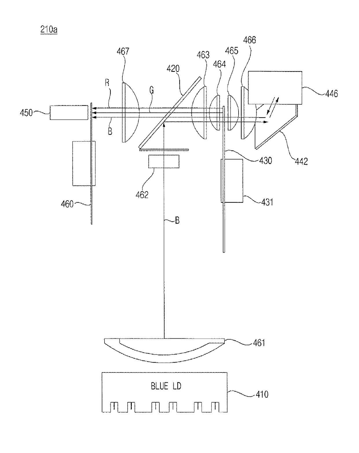
[0027]An optical device as described in this specification is a device that is capable of outputting a visible light. The optical device may be applied to an image projection apparatus. Alternatively, the optical device may be applied to a lighting apparatus.

[0028]Meanwhile, an image projection apparatus as described in this specification is an apparatus that is capable of projecting an image to the outside. For example, the image projection apparatus may be a projector.

[0029]On the other hand, the image projection apparatus as described in this specification may be mounted ...


PUM


Abstract

An optical device and an image projection apparatus including the same are disclosed. The optical device includes a laser diode for outputting a laser light having a predetermined wavelength, a polarization separator for transmitting a first polarized light of the laser light and reflecting a second polarized light of the laser light, a wheel including a wavelength conversion unit for converting a wavelength of the second polarized light of the laser light reflected by the polarization separator such that the second polarized light of the laser light corresponds to one selected from among a blue light, a green light, and a red light and a transmission unit for transmitting the other lights, a polarization converter for converting the light transmitted through the wheel into the first polarized light and outputting the converted first polarized light to the wheel, and an optical output unit for outputting the first polarized light from the polarization converter and the light converted in wavelength and reflected by the wheel. Consequently, it is possible to provide a compact optical device that is capable of achieving highly efficient light output.

Description

TECHNICAL FIELD[0001]The present invention relates to an optical device and an image projection apparatus including the same, and more particularly to a compact optical device that is capable of achieving highly efficient light output and an image projection apparatus including the same.BACKGROUND ART[0002]An image projection apparatus is an apparatus that projects an image. In particular, the image projection apparatus may project an image on a screen.[0003]With the increase in resolution of an image, there is an increasing necessity for achieving highly efficient light output at the time of projecting the image. To this end, it is necessary to efficiently design an optical unit of the image projection apparatus. Much research has been conducted into the optical unit of the image projection apparatus.[0004]Conventionally, lamps, such as a high intensity discharge (HID) lamp, a metal halide lamp, and an ultra high pressure (UHP) lamp, have been used as a light source for high power ...

Claims


Application Information

Patent Timeline
Patent Type & Authority Applications(United States)
IPC IPC(8): H04N9/31G02B5/30G02B27/28G03B21/20G02B26/00
CPCH04N9/3167G03B21/204G02B26/008H04N9/3161G02B5/3083G03B21/2066H04N9/3114G02B27/283G02B27/286G03B21/2073G03B33/08
Inventor JEOUNG, BYUNGWOOYEO, SANGOK
Owner LG ELECTRONICS INC
Why Eureka
Try Eureka