Separator

a technology of separator and spherical rod, which is applied in the direction of centrifuges, rotary centrifuges, etc., can solve the problems of limited local reinforcement, conceivable for limited local reinforcement, and particular outer drums adjacent to the supporting structure, so as to prevent the attempt to disassemble and ensure the effect of sterility and production and mounting

Inactive Publication Date: 2017-07-20
GEA MECHANICAL EQUIP
View PDF6 Cites 21 Cited by
  • Summary
  • Abstract
  • Description
  • Claims
  • Application Information

AI Technical Summary

Benefits of technology

The patent describes a separator that can be used to separate or clarify products. It consists of a rotating drum with a lower and upper part made of plastic. The drum can be designed for single use, which is useful for processing pharmaceutical products without the need for cleaning. The entire drum is sealed, making it hygienic. The technical effect of this design is that it allows for efficient and safe processing of products while minimizing the risk of contamination.

Problems solved by technology

It is, however, also conceivable for limited local reinforcements (further in particular outer drums adjacent to the supporting structure) composed of metal to be provided, for example in the region of seals, in particular in the form of sleeves for reinforcing the pipes at the inside and / or at the outside at the seals.

Method used


Image

  • Separator
  • Separator
  • Separator

Examples


Embodiment Construction

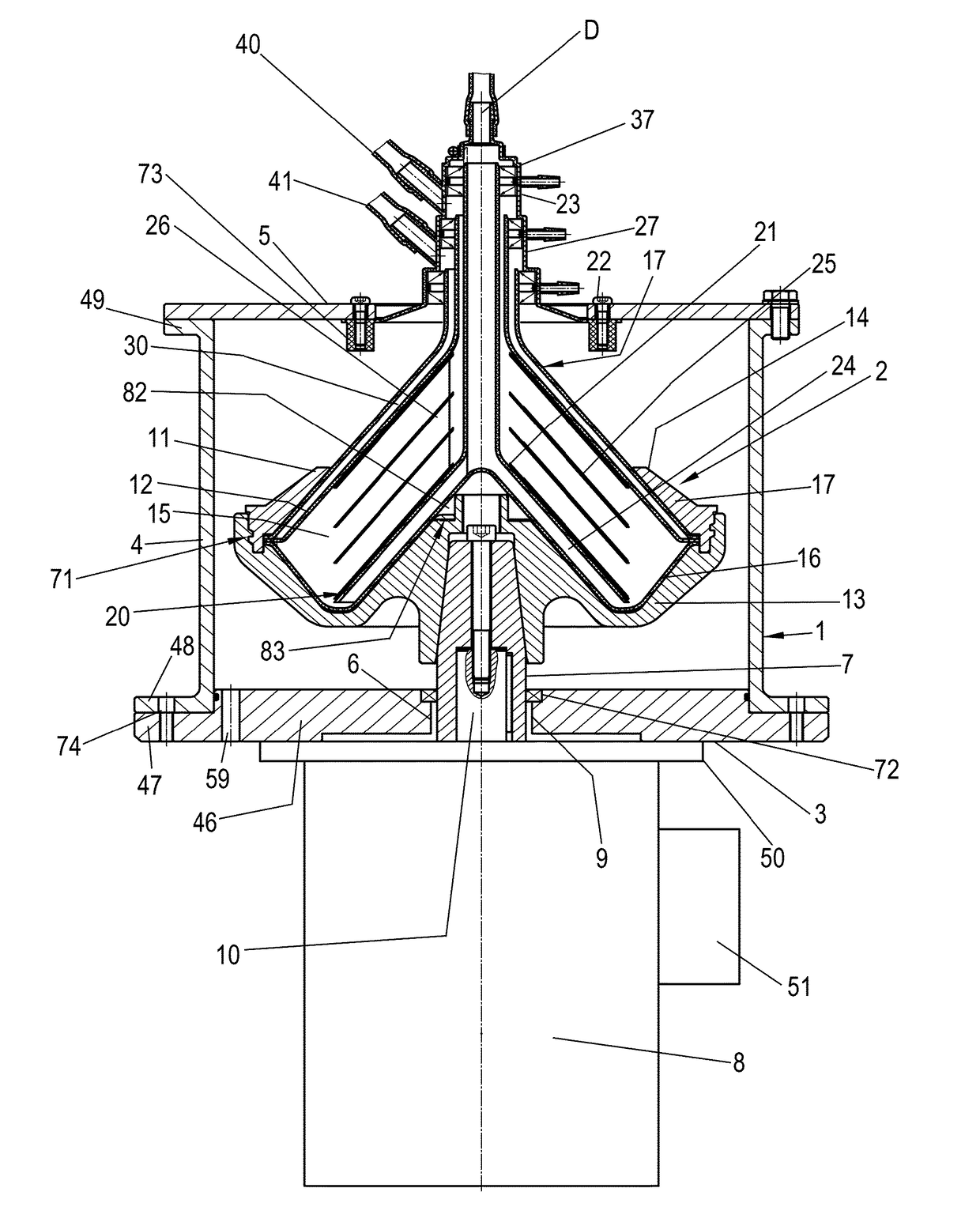
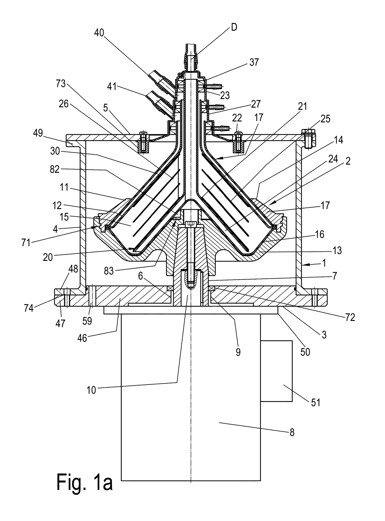
[0044]FIG. 1a shows a section through the region of a housing 1 and of a drum 2 of a separator according to the invention, by means of which a liquid product can, in the centrifugal area, be separated into two phases. The drum 2 has a vertical axis of rotation D. Expressions such as “top” or “bottom” used hereafter relate to the orientation of elements of the separator in relation to the vertical axis of rotation.

[0045]The housing 1 has a lower base part 3, a housing shell part 4 and preferably a top cover 5. The housing shell part 4 and the top cover may advantageously also be formed in one piece.

[0046]The base part 3 has, in turn, a leadthrough 6 through which a rotatable drive spindle 7 extends. A drive motor 8 is preferably arranged directly below the base part 3. The drive motor 8 serves for driving the drive spindle 7. Alternative refinements are conceivable, for example one in which the drive spindle 7 is driven by a drive belt or the like, wherein then, the drive motor is ar...


PUM


Abstract

A separator for the centrifugal processing of a flowable product includes a rotatable drum with a vertical rotation axis. The rotatable drum borders a centrifuge chamber and includes a clarifying arrangement in the drum for clarifying the product to be processed in the centrifugal field. The drum has a separating plane between a drum top part and a drum bottom part. A supply system and the drain system are designed on the drum. The separator also includes a housing in which the drum is arranged, the housing having floor part and a housing shell part connectable to the floor part. A separating plane is likewise designed between the floor part and the housing shell part of the housing. The two separating planes are aligned with each other or there is an offset of less than 250 mm between the two separating planes.

Description

BACKGROUND AND SUMMARY OF THE INVENTION[0001]Exemplary embodiments of the present invention relate to a separator.[0002]Centrifugal separators for realizing continuous operation have long been known, for example in an embodiment as nozzle separators from Japanese patent document JP 62-117649 A. In addition to nozzle separators, separators with solids discharge openings are known which are assigned a hydraulically actuable piston slide by way of which the solids discharge openings can be closed off and opened up. A separator without solids discharge, in an embodiment as a divider, is presented in US patent document U.S. Pat. No. 2,017,734. A separator with screwed-together, solid drum lower and drum upper parts is also presented in US patent document U.S. Pat. No. 2,286,354.[0003]PCT International patent document WO 2014 / 000829 A1 furthermore discloses a generic separator for the separation of a flowable product into different phases or for the clarification of a product, which separ...

Claims


Application Information

Patent Timeline
IPC IPC(8): B04B1/08B04B11/02B04B7/02
CPCB04B1/08B04B11/02B04B7/02B04B7/08
Inventor PENKL, ANDREASQUITER, KATHRINKLEIMANN, THOMASSEDLER, MARIE-THERES
Owner GEA MECHANICAL EQUIP
Why Eureka
Try Eureka