Power control device for vehicle

a power generation control and vehicle technology, applied in the direction of electrochemical generators battery/fuel cell control arrangements, etc., can solve the problems of deteriorating the efficiency of the power generation unit, reducing the efficiency of the output, and limited the range of an efficient rotational speed of the engine, so as to reduce the target charging rate and suppress the power generation output. , the effect of remaining fuel

Active Publication Date: 2017-07-20
MITSUBISHI MOTORS CORP
View PDF12 Cites 13 Cited by
  • Summary
  • Abstract
  • Description
  • Claims
  • Application Information

AI Technical Summary

Benefits of technology

[0012]According to a power control device for a vehicle according to the present invention, the target charging rate decreases as the remaining fuel amount of the power generation unit decreases. Accordingly, the target charging rate is set in such a manner that the target charging rate gradually decreases in accordance with the actuation of the power generation unit. Thus, consumption of the fuel and decrease in the charging rate of the battery progress simultaneously after the power generation start determination is performed, so that a time required for power generation can be secured and the power generation output can be suppressed. Thus, since power can be generated with a suppressed power generation output, the power generation efficiency of the power generation unit can be improved and the amount of power that can be generated with a limited fuel supply can be increased. Consequently, the range of the vehicle can be increased.
[0013]The power generation output of the power generation unit is controlled based on the difference between the target charging rate of the battery and the current charging rate. Accordingly, the control can be accurately performed so that the charging rate of the battery matches the target charging rate of the battery that is set based on the remaining fuel amount.

Problems solved by technology

However, in general, when the output of a fuel cell increases, the efficiency of the output decreases.
Even when the generator for driving the engine is used instead of the fuel cell, the range of an efficient rotational speed of the engine is limited.
This may deteriorate the efficiency of the power generation unit.
Since the fuel of the power generation unit mounted on the vehicle is limited, the deterioration in the efficiency of the power generation unit results in a reduction in the range of the vehicle.

Method used


Image

  • Power control device for vehicle
  • Power control device for vehicle
  • Power control device for vehicle

Examples


Embodiment Construction

[0017]Embodiments of the present invention will be described below with reference to the drawings.

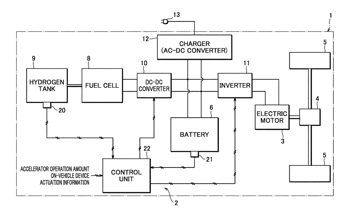
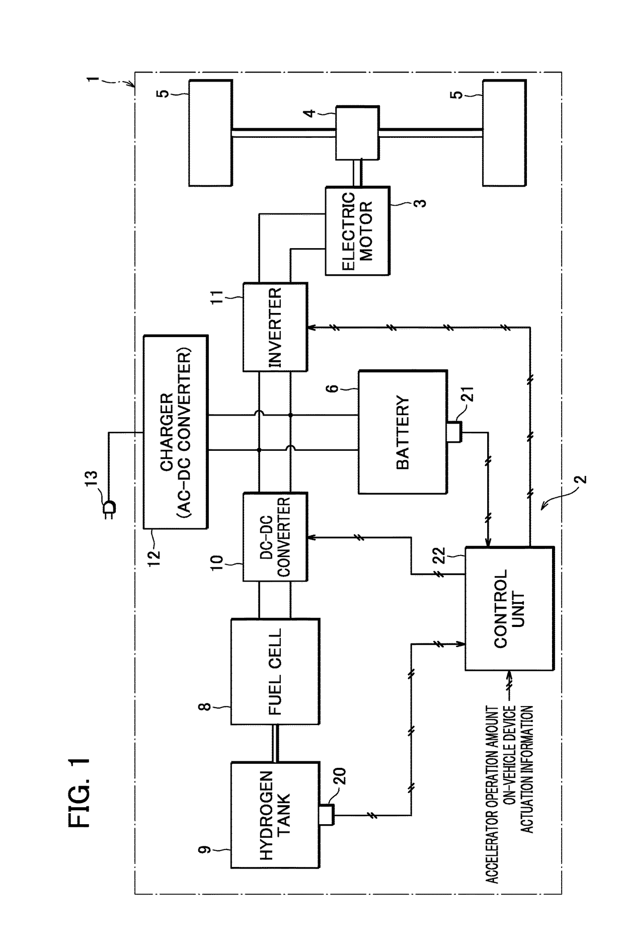
[0018]FIG. 1 is a schematic block diagram showing a drive system of a vehicle 1 according to an embodiment of the present invention.

[0019]The vehicle 1 incorporating a power control device 2 according to an embodiment of the present invention is an electric vehicle including right and left travel wheels 5 that are driven for travelling by an electric motor 3 via a differential gear 4.

[0020]The vehicle 1 incorporates a battery 6 and a fuel cell 8 as a power supply device for supplying power to the electric motor 3 for driving the vehicle to travel.

[0021]The fuel cell 8 generates power using hydrogen stored in a fuel tank 9, which is mounted on the vehicle, as fuel. The power generated by the fuel cell 8 is supplied to the primary side of a DC-DC converter 10 and is boosted, so that the power can be supplied to the electric motor 3 via an inverter 11 from the secondary side of the DC-DC c...


PUM

PropertyMeasurementUnit
poweraaaaaaaaaa
power generationaaaaaaaaaa
current charging rateaaaaaaaaaa

Abstract

In a power control device for a vehicle in which an electric motor for driving the vehicle to travel is supplied with power from a battery mounted on the vehicle and a fuel cell, a control unit sets a target charging rate (SOCt) of the battery in such a manner that the target charging rate decreases as a remaining fuel amount (Qf) of the fuel cell decreases after the power generation of the fuel cell is started during high-output/high-speed travelling and controls a power generation output (Pf) of the fuel cell based on a difference between the target charging rate (SOCt) and a current charging rate (SOC).

Description

BACKGROUND OF THE INVENTION[0001]Field of the Invention[0002]The present invention relates to a power generation control technique for a power generation unit mounted on a vehicle that is driven to travel by an electric motor.[0003]Description of the Related Art[0004]In electric vehicles that travel by driving an electric motor using power supplied from an on-vehicle battery, a vehicle incorporating a range extender serving as a power generation unit has been developed. The range extender is composed of, for example, a generator and a small engine dedicated to power generation. The generated power is supplied to the electric motor and used for charging the on-vehicle battery, thereby making it possible to increase the range of the electric vehicle.[0005]Incidentally, progress has been made in the development of fuel cells recently and vehicles incorporating fuel cells have been proposed. Further, a vehicle using a fuel cell instead of an engine as a range extender for the electric v...

Claims


Application Information

Patent Timeline
Patent Type & Authority Applications(United States)
IPC IPC(8): B60L11/18H01M8/04302H01M8/04858H01M16/00H01M8/04082
CPCB60L11/1881B60L11/1861H01M16/006H01M8/04201H01M8/04932H01M8/04302H01M2250/402B60L2210/30B60L11/1816B60K15/03006B60K2015/03315H01M2250/20H01M2220/20B60L2210/14Y02T10/7072Y02T90/14H01M8/0438H01M8/04597B60L53/14B60L58/12B60L58/40Y02T10/70Y02T10/72Y02T90/40Y02E60/50Y02E60/10B60L58/30Y02T90/12
Inventor KATO, RYOJIICHIKAWA, KOJITAKAHASHI, MASASHINAKANE, KAZUYOSHIKAWASHIMA, KAZUHITOWATANABE, TETSUYATASHIRO, KEISUKE
Owner MITSUBISHI MOTORS CORP
Why Eureka
Try Eureka