Wind-turbine rotor blade, rotor blade trailing edge, method for producing a wind-turbine rotor blade, and wind turbine

a technology of wind turbines and rotor blades, which is applied in the direction of wind motors, wind motors with parallel air flow, motors, etc., can solve the problems of noise emission, disproportionate effort in relation to the effect, and the drop in power output at the trailing edge so as to increase the effectiveness of the rotor blade and reduce the noise emission

Active Publication Date: 2017-07-20
WOBBEN PROPERTIES GMBH
View PDF2 Cites 8 Cited by
  • Summary
  • Abstract
  • Description
  • Claims
  • Application Information

AI Technical Summary

Benefits of technology

[0007]The present invention proposes a solution that further increases the effectiveness of a rotor blade of a wind turbine and reduces the noise emission.
[0008]Consequently, a wind turbine rotor blade has a rotor blade tip, a rotor blade root, a suction side, a pressure side, a rotor blade length, a profile depth and a pitch axis of rotation. The profile depth decreases along the rotor blade length from the rotor blade root to the rotor blade tip. The trailing edge has a trailing edge delimiting line, which replicates the contour of the trailing edge. The trailing edge has a plurality of serrations to improve flow behavior at the trailing edge. The serrations respectively have a serration tip, two serration edges and an angle bisector. The serration edges are provided non-parallel to a direction of incident flow that is perpendicular to the pitch axis of rotation. The serration edges are non-perpendicular to a tangent to the trailing edge delimiting line. The trailing edge delimiting line has a plurality of portions, at least one of the portions extending non-parallel to the pitch axis of rotation.

Problems solved by technology

The difference in pressure between the suction side and the pressure side can cause turbulences to be produced, which may result in an emission of noise and a drop in power output at the trailing edge of the rotor blade.
The provision of the optimum serration geometry at the trailing edge of a rotor blade of a wind turbine may however be an onerous task and there is the risk that it causes a disproportionate effort in relation to the effect.

Method used


Image

  • Wind-turbine rotor blade, rotor blade trailing edge, method for producing a wind-turbine rotor blade, and wind turbine
  • Wind-turbine rotor blade, rotor blade trailing edge, method for producing a wind-turbine rotor blade, and wind turbine
  • Wind-turbine rotor blade, rotor blade trailing edge, method for producing a wind-turbine rotor blade, and wind turbine

Examples


Embodiment Construction

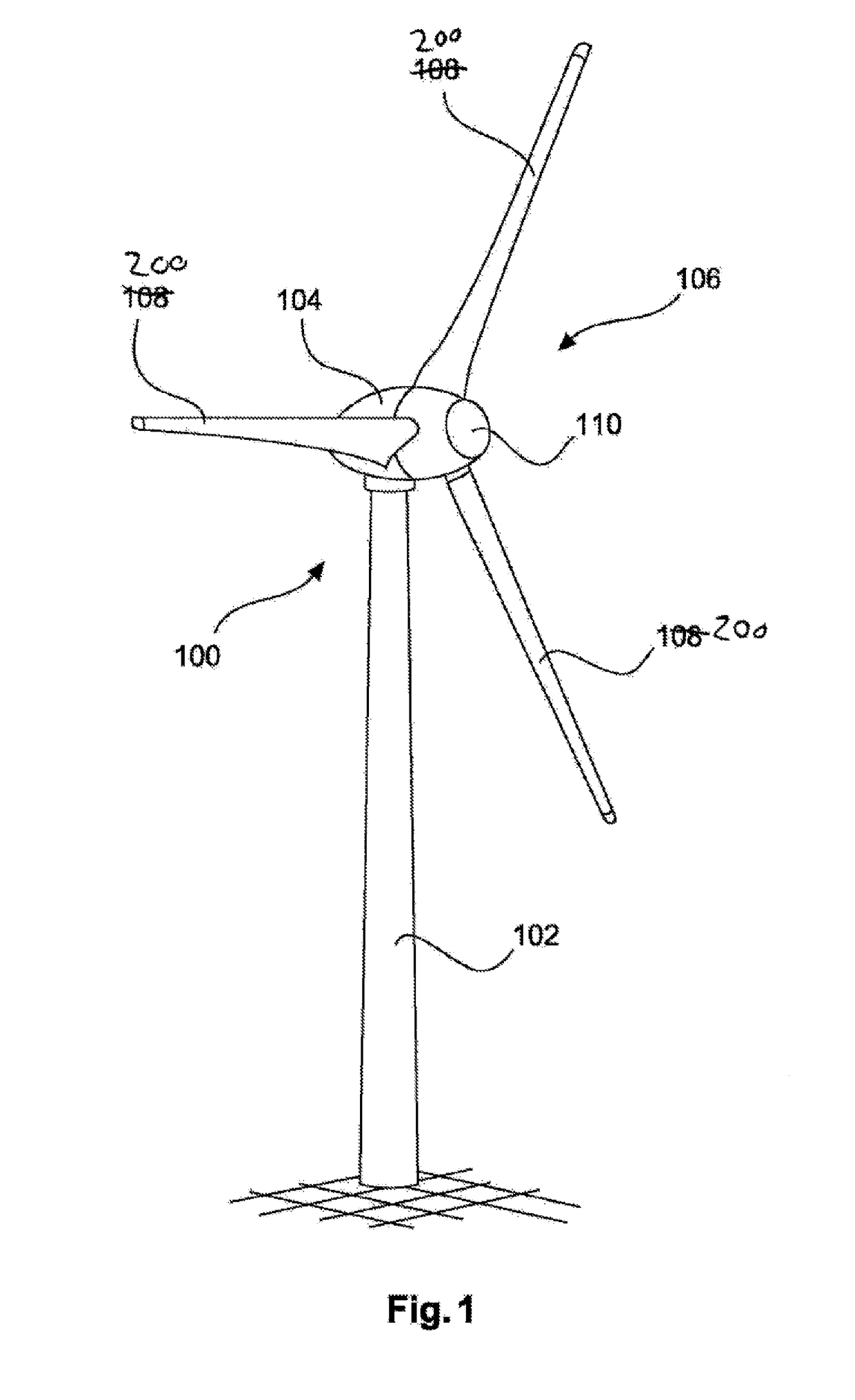
[0048]FIG. 1 shows a wind turbine 100 with a tower 102 and a nacelle 104. Arranged on the nacelle 104 is a rotor 106 with three rotor blades 200 and a spinner 110. During operation, the rotor 106 is set in a rotational movement by the wind and thereby drives a generator in the nacelle 104. The pitch of the three rotor blades can be set for example in each case by a pitch drive.

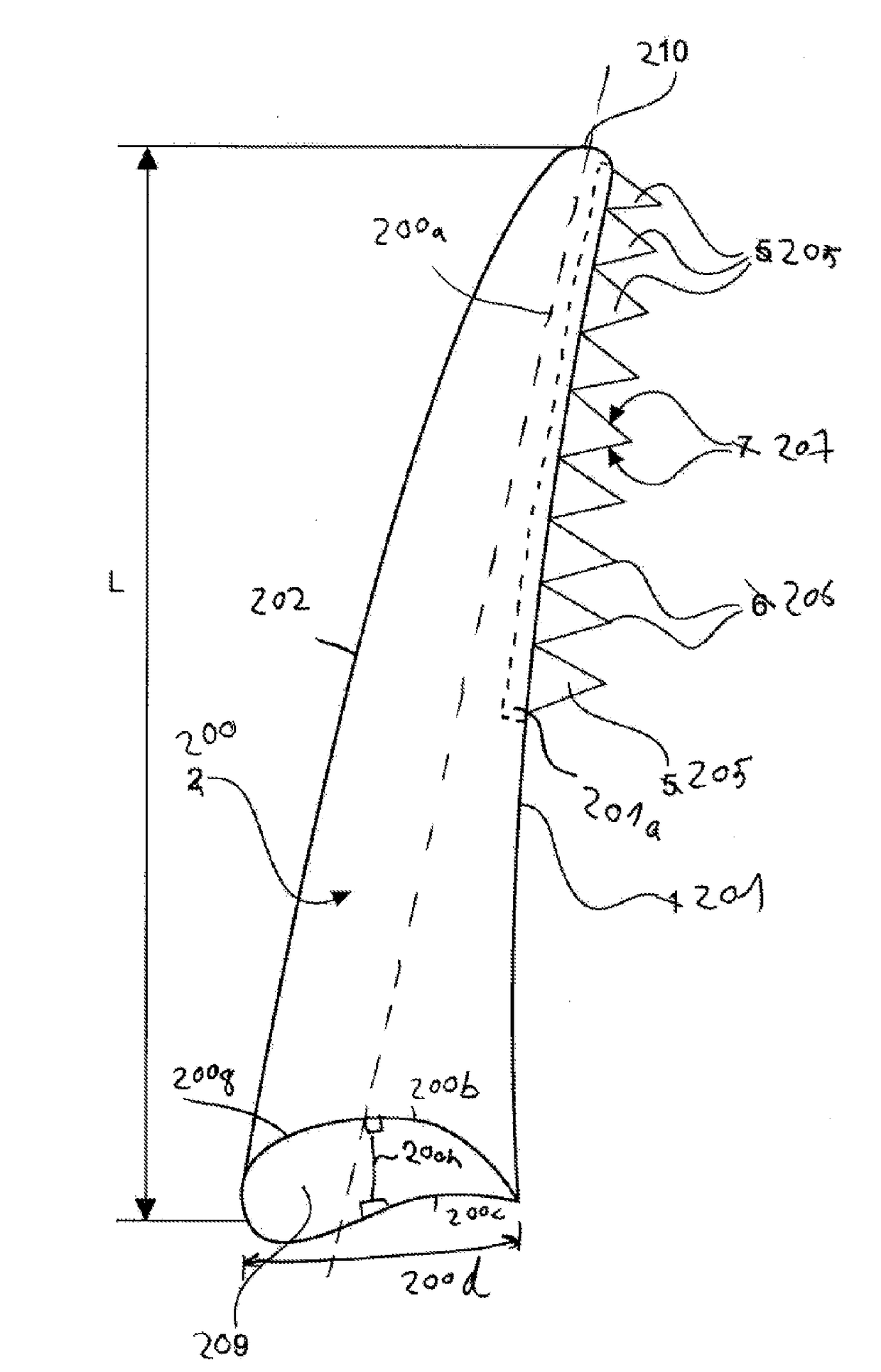
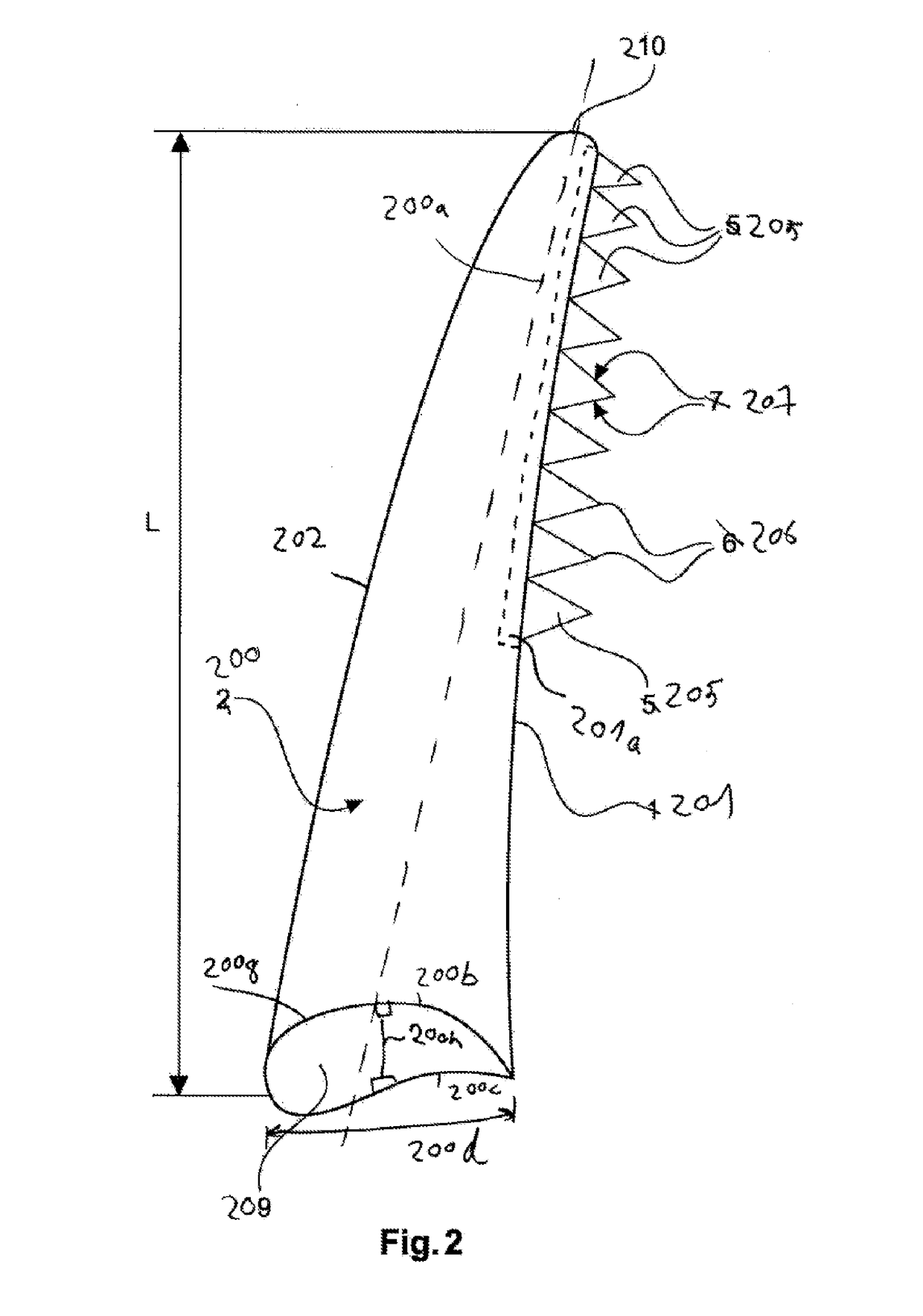
[0049]FIG. 2 schematically shows a wind turbine rotor blade 200 according to a first exemplary embodiment with a rotor blade trailing edge 201, which for simplicity is also referred to as the trailing edge. The rotor blade 200 has a rotor blade root 209 and a rotor blade tip 210. The length between the rotor blade tip 210 and the rotor blade root 209 is referred to as the rotor blade length L. The rotor blade 200 has a pitch axis of rotation 200a. The pitch axis of rotation 200a is the axis of rotation of the rotor blade when the pitch of the rotor blade is adjusted. The rotor blade 200 has a suction side 200b...


PUM


Abstract

A wind turbine rotor blade that has a rotor blade tip, a rotor blade root, a suction side, a pressure side, a rotor blade length, a profile depth and a pitch axis of rotation. The profile depth decreases along the rotor blade length from the rotor blade root to the rotor blade tip. The trailing edge has a trailing edge delimiting line, which replicates the contour of the trailing edge. The trailing edge has a plurality of serrations to improve flow behaviour behavior at the trailing edge. The serrations respectively have a serration tip, two serration edges and an angle bisector. The serration edges are provided non-parallel to a direction of incident flow that is perpendicular to the pitch axis of rotation. The serration edges are non-perpendicular to a tangent to the trailing edge delimiting line. The trailing edge delimiting line has a plurality of portions, at least one of the portions extending non-parallel to the pitch axis of rotation.

Description

BACKGROUND[0001]Technical Field[0002]The invention relates to a trailing edge for a wind turbine rotor blade, to a rotor blade trailing edge and to a wind turbine. The present invention also relates to a method for producing a rotor blade.[0003]Description of the Related Art[0004]Wind turbines are generally known and are designed for example as in FIG. 1. The design of the rotor blade or rotor blades is an important aspect for the efficiency of the wind turbine. The rotor blades of a wind turbine usually have a suction side and a pressure side. The suction side and the pressure side converge at the trailing edge of the rotor blade. The difference in pressure between the suction side and the pressure side can cause turbulences to be produced, which may result in an emission of noise and a drop in power output at the trailing edge of the rotor blade.[0005]In order to reduce the emission of noise and drop in power output, trailing edges with serrations have already been proposed. The e...

Claims


Application Information

Patent Timeline
Patent Type & Authority Applications(United States)
IPC IPC(8): F03D1/06
CPCF03D1/0633F05B2240/221F05B2260/96F05B2250/183F05B2240/30Y02E10/72
Inventor KAMRUZZAMAN, MOHAMMADALTMIKUS, ANDREE
Owner WOBBEN PROPERTIES GMBH
Why Eureka
Try Eureka