Method and apparatus for cryogenic cooling of hts devices immersed in liquid cryogen

a technology of superconductor and liquid cryogen, which is applied in the direction of superconducting magnets/coils, domestic cooling apparatus, magnetic bodies, etc., can solve the problems of complex design of cryogenic apparatus, release of heat from current flowing in the magnet, and complex design of compressor and condenser

Active Publication Date: 2017-07-20
FABRUM IP HLDG LTD
View PDF8 Cites 10 Cited by
  • Summary
  • Abstract
  • Description
  • Claims
  • Application Information

AI Technical Summary

Benefits of technology

[0008]In accordance with one aspect, the disclosure describes a high temperature superconductor apparatus. The apparatus includes a thermally insulated vessel for containing liquid cryogen, and a thermal insulation barrier disposed in the vessel and defining an upper compartment within the vessel above the barrier and a lower compartment within the vessel below the barrier, and the upper compartment is interconnected to the lower compartment by a passage to allow pressure equalization between the upper compartment and the lower compartment. High temperature superconductor is mounted within the lower compartment for immersion in the liquid cryogen. A cryogenic refrigerator has a cold head thermally coupled to the high temperature superconductor for maintaining the high temperature superconductor below a transition temperature for superconductivity. The apparatus also includes a temperature controller for maintaining a temperature of the liquid cryogen in the upper compartment at a temperature of at least a boiling point of the liquid cryogen at atmospheric pressure when the lower compartment and at least a portion of the upper compartment are filled with th

Problems solved by technology

The properties of common materials often change when the materials are cooled to a cryogenic temperature, and these changes complicate the design of cryogenic apparatus.
Otherwise, there is a likelihood that the superconducting magnet may revert to a non-superconducting state, causing a release of heat from current flowing in the magnet.
However, suction pumping requires a continuous supply of liquid nitrogen, or t

Method used


Image

  • Method and apparatus for cryogenic cooling of hts devices immersed in liquid cryogen
  • Method and apparatus for cryogenic cooling of hts devices immersed in liquid cryogen
  • Method and apparatus for cryogenic cooling of hts devices immersed in liquid cryogen

Examples


Embodiment Construction

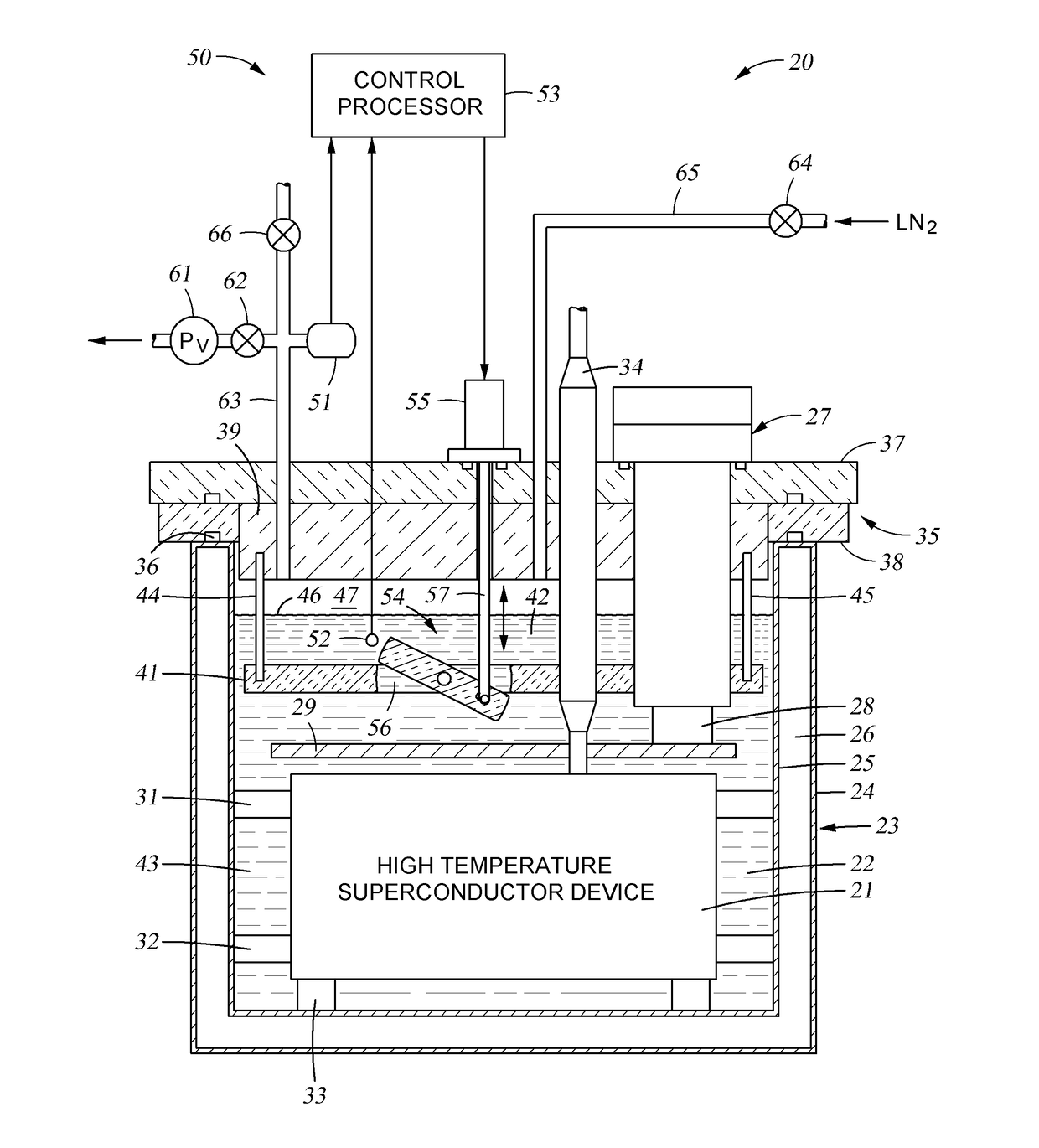
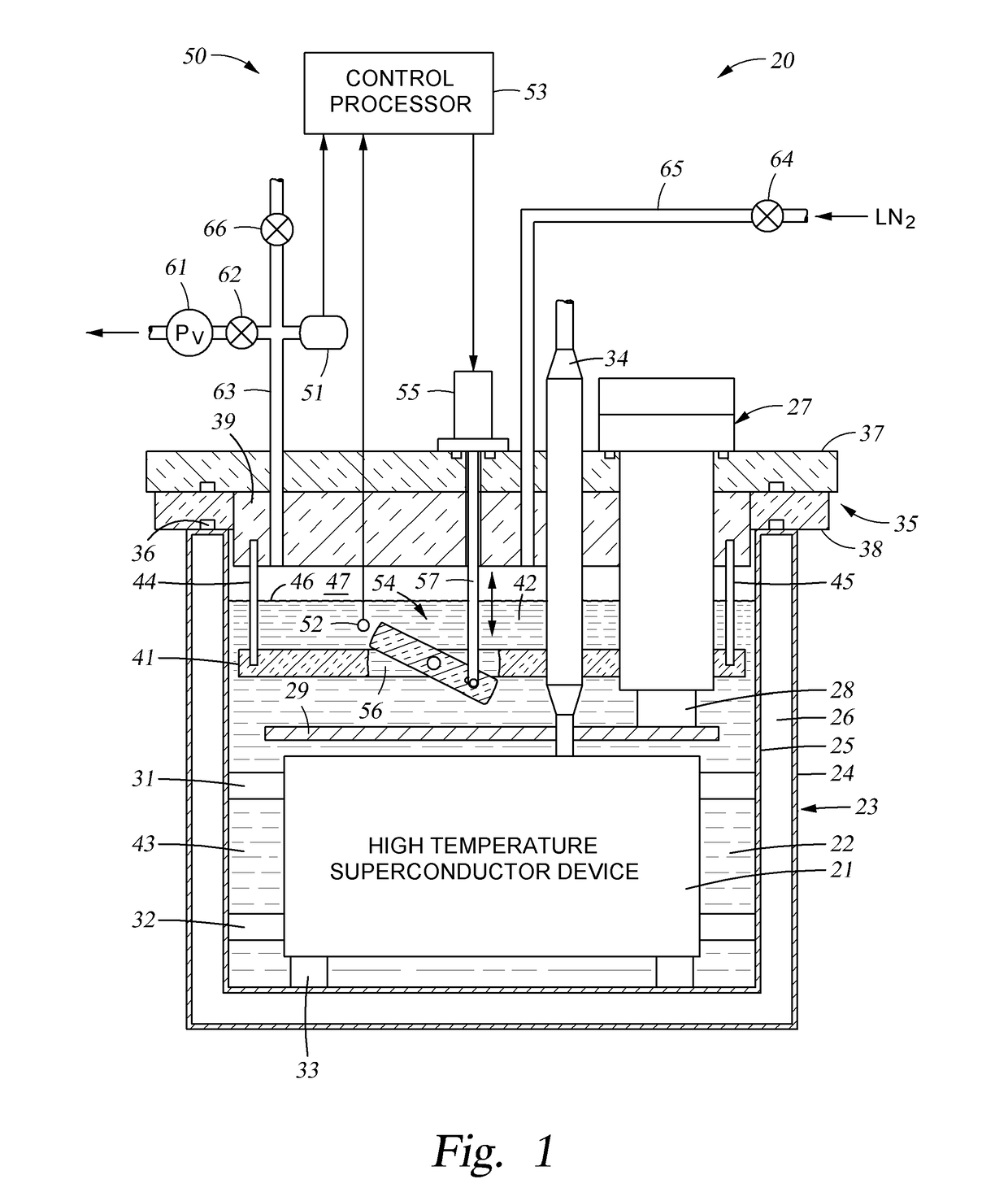
[0017]With reference to FIG. 1, there is shown a high temperature superconducting apparatus 20 including a high temperature superconductor (HTS) device 21 immersed in liquid cryogen 22. For example, the liquid cryogen is liquid nitrogen, the HTS of the device 21 includes windings of Bi2223 or REBCO HTS, and the device 21 is a superconducting magnet, a superconducting fault current limiter, or a superconducting energy storage inductor.

[0018]In FIG. 1, the liquid cryogen 22 is contained in a thermally insulated vessel 23 functioning as a cryostat. In this example, the vessel 23 is cylindrical and has an outer wall 24, and inner wall 25 jointed to the outer wall at the top of the vessel, and an evacuated space 26 between the inner and outer walls. For example, the inner wall 24 and the outer wall 25 are made of stainless steel.

[0019]For the reasons discussed above, it is desired to cool the HTS device 21 to a temperature below the boiling point of the liquid cryogen at the pressure wit...


PUM


Abstract

A thermally insulated vessel contains a thermal insulation barrier defining an upper compartment above the barrier and a lower compartment below the barrier. The compartments are interconnected by a passage to allow pressure equalization. High temperature superconductor is mounted within the lower compartment for immersion in the liquid cryogen. A cryogenic refrigerator has a cold head thermally coupled to the high temperature superconductor for maintaining the high temperature superconductor below a superconductive transition temperature. A temperature controller maintains a temperature of the liquid cryogen in the upper compartment at a temperature of at least a boiling point of the liquid cryogen at atmospheric pressure when the lower compartment and at least a portion of the upper compartment are filled with the liquid cryogen.

Description

TECHNICAL FIELD[0001]This disclosure relates to a method and apparatus for cryogenic cooling of high temperature superconductor (HTS) devices immersed in liquid cryogen.BACKGROUND ART[0002]The properties of common materials often change when the materials are cooled to a cryogenic temperature, and these changes complicate the design of cryogenic apparatus. These changes become substantial below a temperature of about 150 degrees Kelvin. Therefore, in this disclosure, “cryogenic” relates to a temperature below 150 degrees Kelvin. For example, “cryogenic liquid” is a liquid that has a boiling point below 150 degrees Kelvin. Examples of cryogenic liquid include liquid helium, hydrogen, neon, nitrogen, fluorine, argon, oxygen, and krypton.[0003]High temperature superconductor (HTS) is a superconductor having a transition temperature above thirty degrees Kelvin (−243.2° C.). The transition temperature is the temperature below which the superconductor becomes superconducting in the absenc...

Claims


Application Information

Patent Timeline
IPC IPC(8): F25B19/00H01F6/04F25D17/02F25D19/00F25D29/00
CPCF25B19/005F25D19/00F25D29/001F25D2400/02H01F6/04F25D2700/121F25D17/02
Inventor STAINES, MICHAEL
Owner FABRUM IP HLDG LTD
Why Eureka
Try Eureka