Active cancellation of transmitter leakage in a radio receiver

Active Publication Date: 2017-07-20
TELEFON AB LM ERICSSON (PUBL)
View PDF1 Cites 7 Cited by
  • Summary
  • Abstract
  • Description
  • Claims
  • Application Information

AI Technical Summary

Benefits of technology

[0008]Systems and methods are disclosed for active cancellation of transmitter leakage in a radio receiver that reduce power consumption, reduce noise in a desired receive frequency band, or both. In some embodiments, in order to cancel, or mitigate, transmitter leakage in a receive path, a transmitter leakage cancellation signal is injected into the receive path in an upstream, or reverse, direction. By injecting the transmitter leakage cancellation signal in the upstream direction, a noise component of the transmitter leakage cancellation signal propagates through the receive path in the upstream direction and is either passed through a receive antenna or attenuated by an upstream component. Conversely, a desired component of the transmitter leakage cancellation signal is reflected by an upstream filter and, thereafter propagates through the receive path in the downstream direction to thereby cancel, or mitigate, the transmitter leakage in the receive path. In this manner, active transmitter leakage cancellation can be performed while minimizing degradation of receiver sensitivity.
[0009]In one embodiment, a radio system includes a receive path including a receive filter in the receive path having a pass-band that corresponds to a desired receive frequency band. In addition, the receive pa

Problems solved by technology

However, because the radio transmitter typically outputs signals at a power level that is much higher than that of desired signals received by the radio receiver, the radio receiver typically suffers from self-interference, or leakage, from the radio transmitter.
However, the duplexer provides limited isolation between the radio transmitter and the radio receiver.
As such, transmitter leakage occurs from the radio transmitter to the radio receiver through the duplexer.
Transmitter leakage may also occur even in implementations where the radio transmitter and the radio receiver are not directly connected (i.e., there is no duplexer and no antenna sharing between the radio transmitter and the radio receiver) or may also occur due to crosstalk leaking through integrated circuit substrates, device packages, or pri

Method used


Image

  • Active cancellation of transmitter leakage in a radio receiver
  • Active cancellation of transmitter leakage in a radio receiver
  • Active cancellation of transmitter leakage in a radio receiver

Examples


Embodiment Construction

[0023]The embodiments set forth below represent information to enable those skilled in the art to practice the embodiments and illustrate the best mode of practicing the embodiments. Upon reading the following description in light of the accompanying drawing figures, those skilled in the art will understand the concepts of the disclosure and will recognize applications of these concepts not particularly addressed herein. It should be understood that these concepts and applications fall within the scope of the disclosure and the accompanying claims.

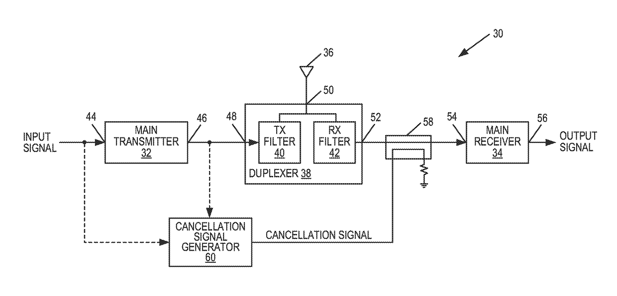
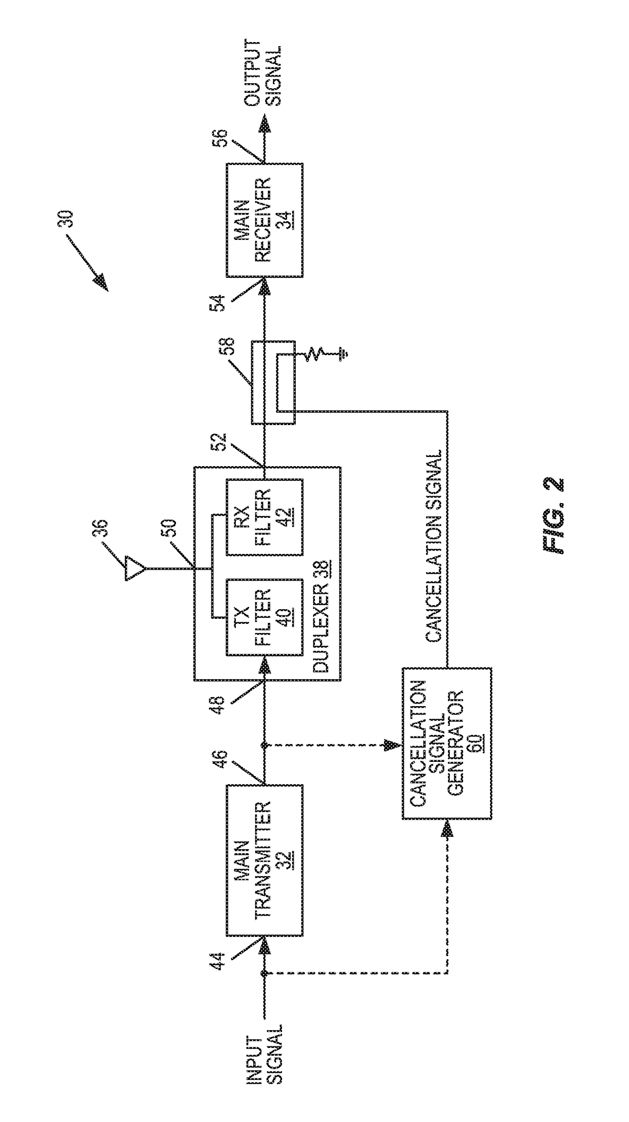
[0024]Systems and methods are disclosed for active cancellation of transmitter leakage in a radio receiver that reduce power consumption, reduce noise in a desired receive frequency band, or both. In some embodiments, in order to cancel, or mitigate, transmitter leakage in a receive path, a transmitter leakage cancellation signal (hereinafter referred to simply as “cancellation signal”) is injected into the receive path in an upstream, or ...


PUM


Abstract

Systems and methods are disclosed for active cancellation of transmitter leakage in a radio receiver that reduce power consumption and/or reduce noise in a desired receive frequency band. In some embodiments, in order to cancel transmitter leakage in a receive path, a cancellation signal is injected into the receive path in an upstream direction. By injecting the cancellation signal in the upstream direction, a noise component of the cancellation signal propagates through the receive path in the upstream direction and is either passed through a receive antenna or attenuated by an upstream component. Conversely, a desired component of the cancellation signal is reflected by an upstream filter and, thereafter, propagates through the receive path in the downstream direction to thereby cancel the transmitter leakage in the receive path. In this manner, active transmitter leakage cancellation can be performed while minimizing degradation of receiver sensitivity.

Description

FIELD OF THE DISCLOSURE[0001]The present disclosure relates to active cancellation of transmitter leakage in a radio receiver.BACKGROUND[0002]Wireless communications systems operate according to either a Time Division Duplexing (TDD) scheme or a Frequency Division Duplexing (FDD) scheme. For the FDD scheme, full duplex operation is typically desired, i.e., a radio transceiver is required to simultaneously transmit and receive in different frequency bands, which are referred to as a Transmit (TX) frequency band and a Receive (RX) frequency band, respectively. However, because the radio transmitter typically outputs signals at a power level that is much higher than that of desired signals received by the radio receiver, the radio receiver typically suffers from self-interference, or leakage, from the radio transmitter. In particular, a duplexer is often used to allow the radio transmitter and the radio receiver to share the same antenna. However, the duplexer provides limited isolatio...

Claims


Application Information

Patent Timeline
IPC IPC(8): H04B1/525H04L5/14
CPCH04L5/14H04B1/525
Inventor WYVILLE, MARK
Owner TELEFON AB LM ERICSSON (PUBL)
Why Eureka
Try Eureka