
Method for characterizing and exploiting a subterranean formation comprising a network of fractures

a fracture network and subterranean technology, applied in the oil industry, can solve the problems of not being able to accurately represent the reality of fractured media, not being able to access the plane perpendicular to the layers (often a sub-vertical plane), and being relatively expensiv

Active Publication Date: 2017-07-27
INST FR DU PETROLE
View PDF2 Cites 9 Cited by
  • Summary
  • Abstract
  • Description
  • Claims
  • Application Information

AI Technical Summary

Benefits of technology

The patent text describes a method for predicting and optimizing the exploitation of fractured reservoirs to improve the flow rates and quantities of hydrocarbons. The method involves calculating the behavior of the reservoir using a given production scenario, which takes into account the distribution and behavior of fractures. This knowledge helps to optimize the production schemes, such as the number and location of wells, the type of recovery fluid injected, etc. The geometry of the fracture network also plays a role in determining the movement of fluids at the reservoir scale, which is important for calibrating models and predicting future production. Geosciences specialists use three-dimensional images to locate a large number of fractures. Overall, the patent text provides a technical solution for better understanding and managing fractured reservoirs for improved oil and gas production.

Problems solved by technology

The size of blocks in the plane of each layer is then relatively well characterized but that in a plane perpendicular to the layers (often a sub-vertical plane) is not accessible.
This approach is therefore a 2D approach, which does not make it possible to represent correctly the reality of the fractured media.
Moreover, this method necessitates image analysis (pixelization) for each layer and is therefore relatively costly.
The major defect of this method is that it does not take into account the connectivity of the network of fractures.
The second defect is that it yields a result that is a function of the position and the density of the rays that are traced.

Method used


Image

  • Method for characterizing and exploiting a subterranean formation comprising a network of fractures
  • Method for characterizing and exploiting a subterranean formation comprising a network of fractures
  • Method for characterizing and exploiting a subterranean formation comprising a network of fractures

Examples


application example

[0137]The features and advantages of the method according to the invention will become more clearly apparent on reading the following application examples.

[0138]The present invention was applied to a subterranean formation comprising ten layers. The meshed representation of this formation consisted of 1 050 000 meshes (350×300×10).

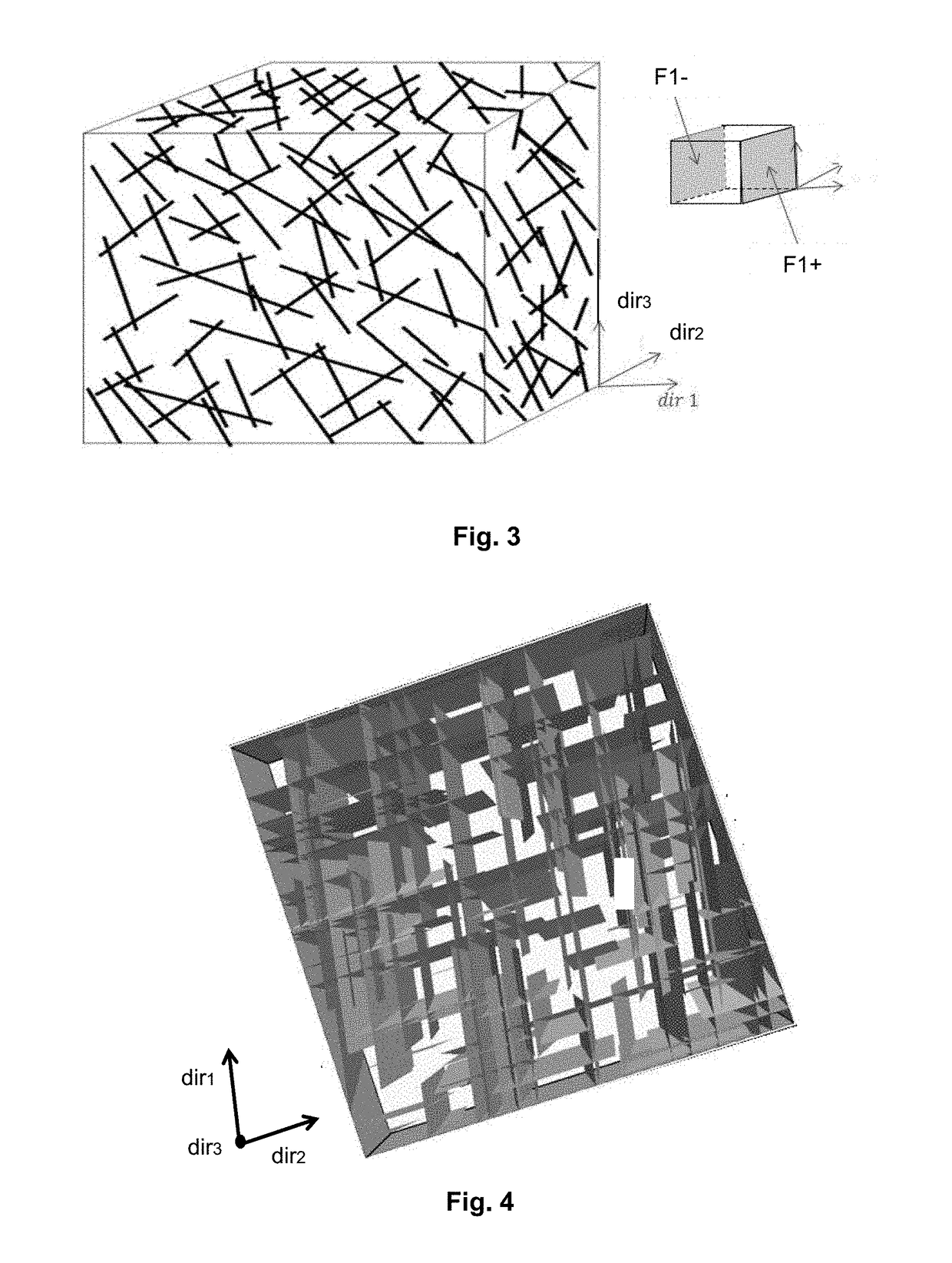
[0139]In a first example, it was considered that the subterranean formation was characterized by two families of structures:[0140]a first family, having a spacing between fractures of 5 m, the fractures of this family having a mean length of 20 m and a mean orientation of 10°;[0141]a second family, having a spacing between fractures of 3 m, the fractures of this family having a mean length of 45 m and a mean orientation of 100°.

[0142]FIG. 4 shows by way of illustration the distribution of these two families of fractures in said formation. It can notably be seen in this figure that the two families of fractures are substantially mutually orthogonal. This fi...


PUM


Abstract

Method for exploiting a fluid in a subterranean formation comprising a network of fractures.On the basis of measurements of properties relating to the formation, a meshed representation of the formation, and statistical parameters relating to the network of fractures, each mesh of the meshed representation is broken down into at least one unfractured matrix block and an equivalent permeability tensor of the network of fractures in the mesh concerned is determined. A matrix block characteristic dimension is then determined according to a relation that is a function at least of the eigenvalues of the equivalent permeability tensor. On the basis of the meshed representation, the characteristic dimension and a flow simulator, there is defined an optimum exploitation scheme for the fluid of the formation and said fluid is exploited as a function of the optimum exploitation scheme.Application notably to oil exploration and exploitation.

Description

[0001]The present invention concerns the oil industry and more particularly the exploration and exploitation of hydrocarbon deposits and geological gas storage sites.[0002]The invention concerns in particular a method for constructing a representation of a subterranean formation crossed by any network of fractures and the use of that representation for the simulation of the flows of fluid in the formation concerned.[0003]The petroleum industry and more specifically the exploration and exploitation of wells, notably oil wells, necessitate the acquisition of as precise as possible a knowledge of the subterranean geology in order to provide effective evaluation of the reserves, modeling of production or management of exploitation. In fact, the determination of the location of a production or injection well in a hydrocarbon deposit, the constitution of the drilling sludge, the completion characteristics, the choice of a method of recovering the hydrocarbons (such as the injection of wat...

Claims


Application Information

Patent Timeline
Patent Type & Authority Applications(United States)
IPC IPC(8): G01V99/00G06F17/16G06F17/50
CPCG01V99/005G06F2217/16G06F17/16G06F17/5009E21B43/00G01V3/38G01V20/00G01V11/00G06F30/20G06F2111/10G01V2210/646
Inventor JERBI, CHAHIRFOURNO, ANDRENOETINGER, BENOIT
Owner INST FR DU PETROLE
Learn More