
Multifrequency capacitively coupled plasma etch chamber

a capacitively coupled, plasma technology, applied in the direction of coating, chemical vapor deposition coating, plasma technique, etc., can solve the problem that the plasma processing system does not offer sufficient scaling and transferability of current processes

Inactive Publication Date: 2017-07-27
LAM RES CORP
View PDF11 Cites 12 Cited by
  • Summary
  • Abstract
  • Description
  • Claims
  • Application Information

AI Technical Summary

Benefits of technology

The present invention aims to provide a capacitively coupled plasma processing system that can be used for different substrate diameters while maintaining uniformity in plasma density and distribution. The technical effects of this invention include scaling and transferability of current processes, as well as improved control over plasma uniformity, density, and radial distribution for large substrate diameters.

Problems solved by technology

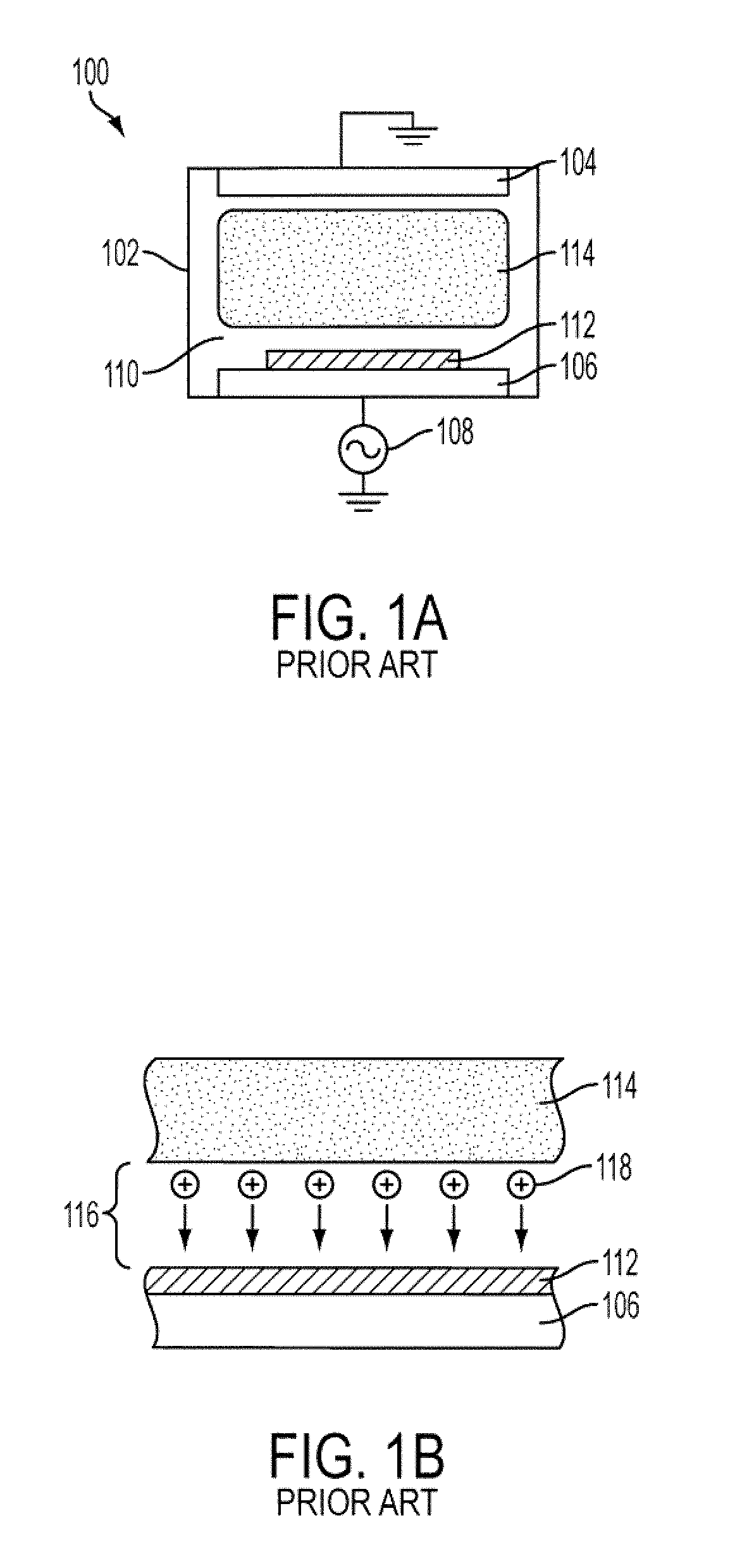
Unfortunately, the aforementioned plasma processing systems do not offer sufficient scaling and transferability of current processes for large substrate diameters.

Method used


Image

  • Multifrequency capacitively coupled plasma etch chamber
  • Multifrequency capacitively coupled plasma etch chamber
  • Multifrequency capacitively coupled plasma etch chamber

Examples


Embodiment Construction

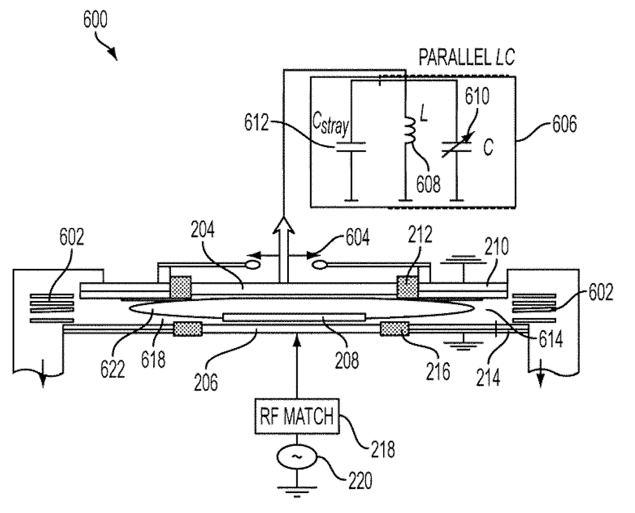
[0044]FIG. 6 illustrates a plasma processing system 600 in accordance with an example embodiment of the present invention. As illustrated in FIG. 6, plasma processing system 600 includes upper electrode 204, lower electrode 206, RF matching circuit 218, RF generator 220, upper insulator 212, bottom insulator 216, grounded bottom extension ring 214, grounded upper extension ring 210, a set of confinement rings 602, an RF ground device 604 and a resonant filter 606. Resonant filter 606 includes an inductor 608, a variable capacitor 610 and a stray capacitance 612. In plasma processing system 600, a substrate 208 may be disposed above lower electrode 206 for processing.

[0045]RF generator 220 provides RF power to lower electrode 206 through RF matching circuit 218. Non-limiting examples of radio frequencies supplied by RF generator 220 include 2, 27 and 60 MHz.

[0046]Upper electrode 204 opposes lower electrode 206 and is capacitively coupled thereto. Upper electrode 204 is additionally c...


PUM

PropertyMeasurementUnit
radio frequenciesaaaaaaaaaa

Abstract

A plasma processing system for use with a gas. The plasma processing system comprises a first electrode, a second electrode, a gas input port, a power source and a passive circuit. The gas input port is operable to provide the gas between the first electrode and the second electrode. The power source is operable to ignite plasma from the gas between the first electrode and the second electrode. The passive circuit is coupled to the second electrode and is configured to adjust one or more of an impedance, a voltage potential, and a DC bias potential of the second electrode. The passive radio frequency circuit comprises a capacitor arranged in parallel with an inductor.

Description

[0001]The present application claims benefit under 35 U.S.C. §119 (e) to U.S. provisional patent application 61 / 166,994, filed Apr. 6, 2009, the entire disclosure of which is incorporated herein by reference.BACKGROUND[0002]Advances in plasma processing have facilitated growth in the semiconductor industry. Plasma processing may involve different plasma generating technologies, for example, inductively coupled plasma processing systems, capacitively-coupled plasma processing systems, microwave generated plasma processing systems and the like. Manufacturers often employ capacitively-coupled plasma processing systems in processes that involve etching and / or depositing of materials to manufacture semiconductor devices.[0003]Next-generation semiconductor devices being fabricated with new advanced materials, complex stacks of dissimilar materials, thinner layers, smaller features, and tighter tolerances may require plasma processing systems with more exact control and wider operating win...

Claims


Application Information

Patent Timeline
Patent Type & Authority Applications(United States)
IPC IPC(8): H01L21/306C23C16/513
CPCH01L21/2633C23C16/5096H01J37/32091H01J37/32165H01J37/32174H01J37/32532H01J37/32577H01L21/205H01L21/02H01L21/3065H01L21/76825H01L21/76826H05H1/34H05H1/36
Inventor MARAKHTANOV, ALEXEIDHINDSA, RAJINDERKOSHIISHI, AKIRAFISCHER
Owner LAM RES CORP
Learn More