Antenna module and electronic device

an antenna module and electronic device technology, applied in the direction of non-resonant long antennas, instruments, sensing by electromagnetic radiation, etc., can solve the problems of reducing reducing the antenna characteristics, and increasing so as to improve the antenna characteristics, increase the antenna coil size, and reduce the size of the antenna coil

Inactive Publication Date: 2017-07-27
MURATA MFG CO LTD
View PDF1 Cites 4 Cited by
  • Summary
  • Abstract
  • Description
  • Claims
  • Application Information

AI Technical Summary

Benefits of technology

[0017]According to preferred embodiments of the present invention, a relative increase in the size of an antenna coil provides improved and increased antenna characteristics. Without reducing the size of the antenna coil, the antenna module may be reduced in size. In addition, wiring conductors are disposed far from mounting electrodes and terminal electrodes, enabling a high v...

Problems solved by technology

Therefore, an antenna module having surface-mounted devices becomes larger due to the size of the above-described insulator layers.
An attempt to reduce the antenna module in size so as to cancel the increase in size leads to a reduction in the size of the antenna coil, resulting in degradation in antenna characteristic...

Method used


Image

  • Antenna module and electronic device
  • Antenna module and electronic device
  • Antenna module and electronic device

Examples


first preferred embodiment

[0026]A first preferred embodiment of the present invention provides an antenna module that may be used, for example, in RFID communications on a HF band. The HF band may be, for example, the 13.56 MHz band.

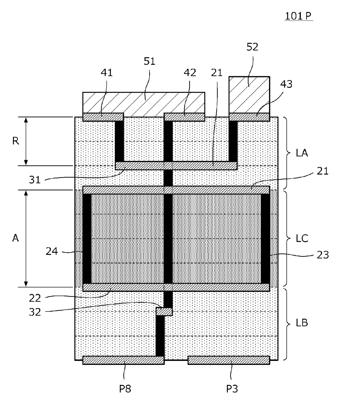
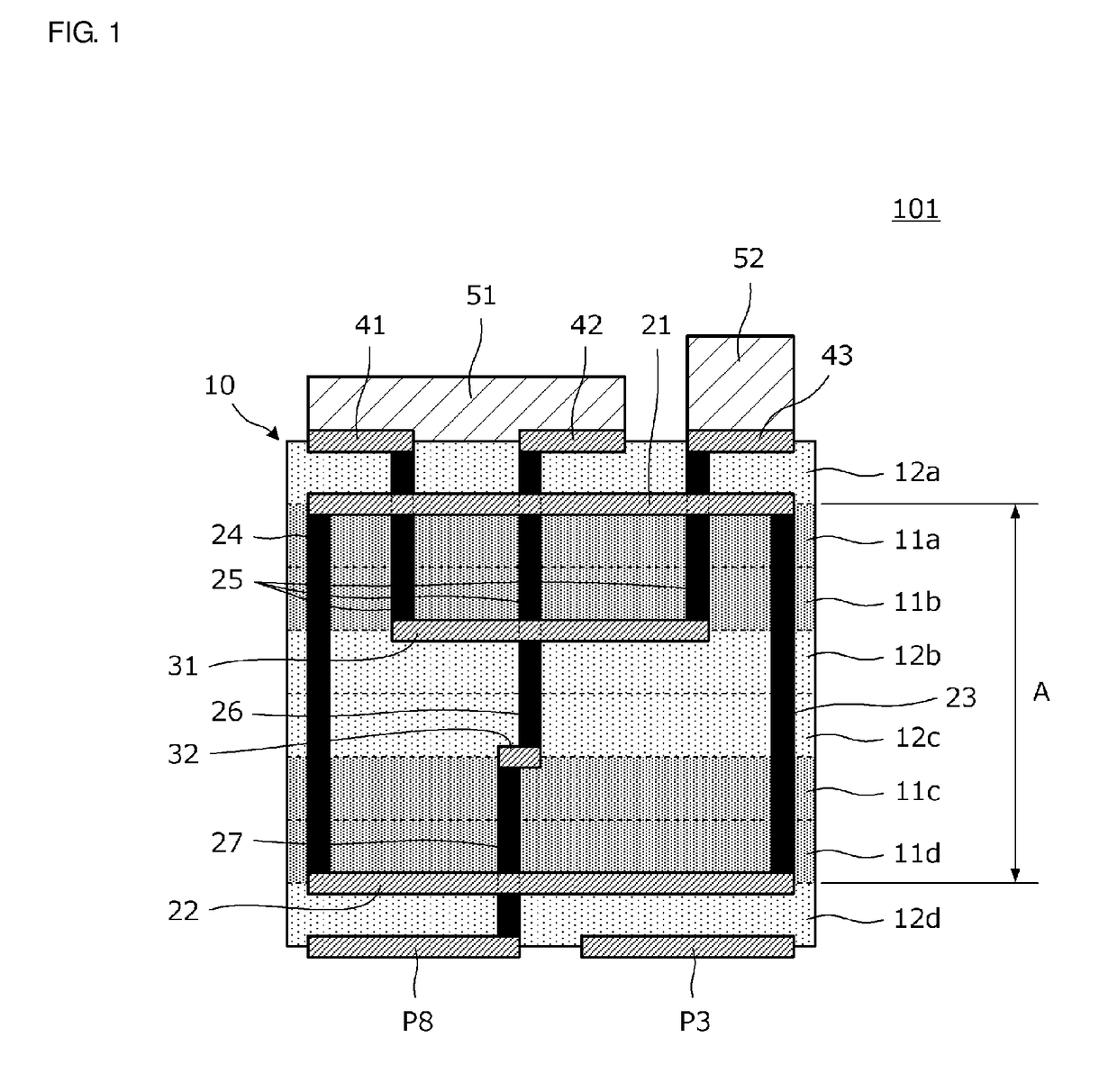
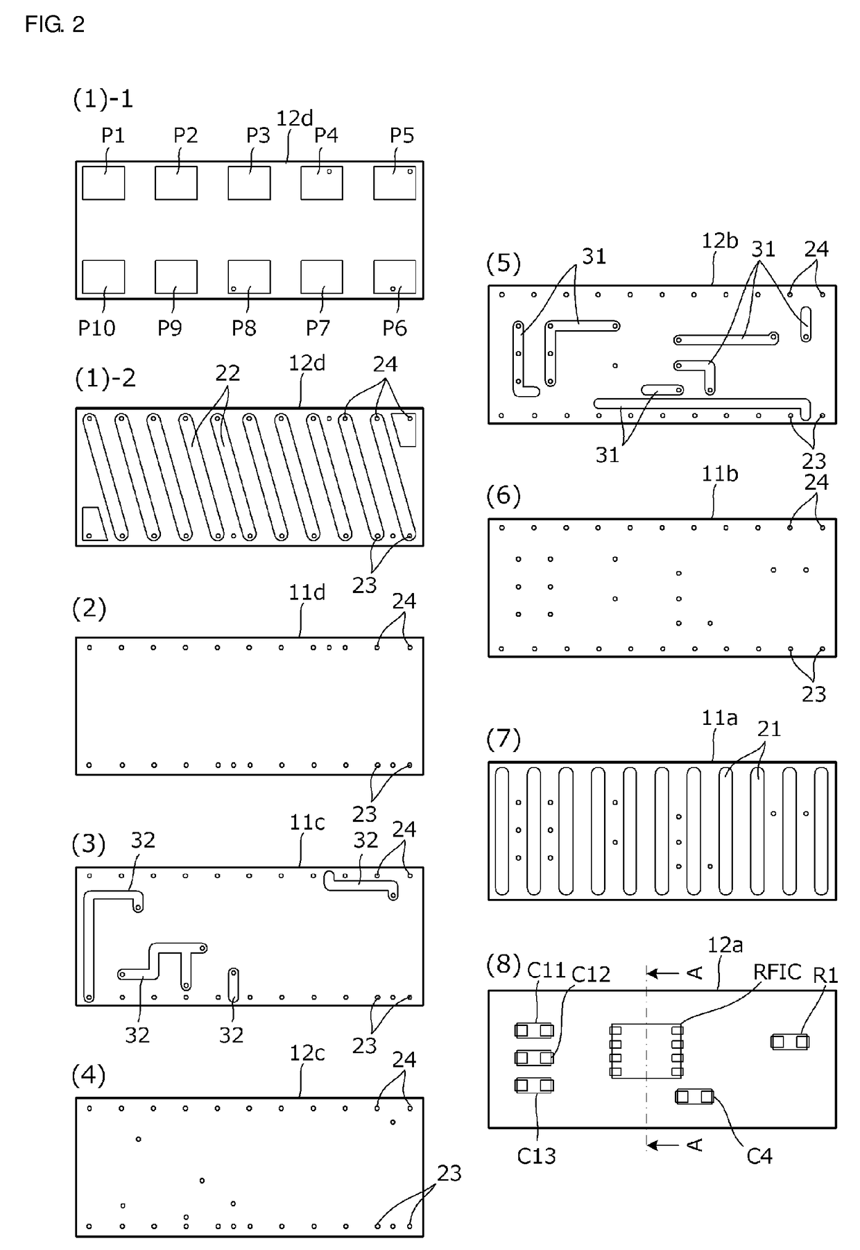
[0027]FIG. 1 is a cross-sectional view of a portion of the inside of an antenna module 101 according to the first preferred embodiment, in the winding axis direction of an antenna coil. FIG. 2 is a plan view of the layers of the antenna module 101 before lamination. FIG. 7 is a cross-sectional view of a portion of the inside of an antenna module 101P, which is a comparison target, in the winding axis direction of an antenna coil. FIGS. 1 and 7 are provided for simplicity of description regarding the first preferred embodiment, and the wiring arrangement, connections, and the like in the antenna module 101 shown in FIG. 2 do not completely match the wiring arrangement, connections, and the like in FIGS. 1 and 7 for clarity.

[0028]As shown in FIG. 1, the antenna module 101 according...

second preferred embodiment

[0051]FIG. 4 is a cross-sectional view of a portion of the inside of an antenna module 102 according to a second preferred embodiment of the present invention, in the winding axis direction of the antenna coil. Compared with the antenna module 101 shown in FIG. 1 in the first preferred embodiment, the positions at which the wiring conductors 32 are provided is different in the second preferred embodiment. In addition, the second preferred embodiment includes a resin cover 60 provided on the top surface of the multilayer body 10. FIG. 4 is a view provided for simplicity of description regarding the second preferred embodiment, and the wiring arrangement, connections, and the like in the antenna module 101 shown in FIG. 2 do not completely match the wiring arrangement, connections, and the like in FIG. 4 for clarity.

[0052]As shown in FIG. 4, some of the wiring conductors 31 may be disposed within the nonmagnetic layers 12b and 12c, for example. Thus, no magnetic body or element is loc...

third preferred embodiment

[0055]In a third preferred embodiment of the present invention, an antenna module including an antenna coil with a coil winding axis extending in the laminating direction of the insulator layers is described below.

[0056]FIG. 5 is an exploded perspective view of an antenna module 103 according to the third preferred embodiment.

[0057]As shown in FIG. 5, the antenna module 103 according to the third preferred embodiment includes a multilayer body in which the insulator layers 12a, 11a, 11b, 12b, 12c, 11c, 11d, and 12d are laminated, the surface-mounted devices 51 and 52 mounted on the top surface of the multilayer body, an antenna coil with a coil winding axis extending in the laminating direction of the insulator layers, and wiring conductors 31, 32a, and 32b electrically connected with the surface-mounted devices 51 and 52 or the antenna coil.

[0058]The antenna coil includes multiple coil conductors 28a, 28b, 28c, 28d, 28e, 28f, and 28g provided on the insulator layers 11a, 11b, 12b, ...


PUM


Abstract

An antenna module includes a multilayer body of laminated insulator layers, surface-mounted devices on a top surface of the multilayer body, an antenna coil with a coil winding axis extending in the laminating direction of the insulator layers or in a direction parallel or substantially parallel to the insulator layers, and wiring conductors electrically connected with the surface-mounted devices or the antenna coil. The antenna coil includes coil conductors on more than one of the insulator layers, and interlayer connection conductors, each of which electrically connects end portions of corresponding ones of the coil conductors to each other, to define a helical shape. The wiring conductors are within a space defined through formation of the antenna coil, in the laminating direction of the insulator layers.

Description

CROSS REFERENCE TO RELATED APPLICATIONS[0001]This application claims the benefit of priority to Japanese Patent Application No. 2014-255624 filed on Dec. 17, 2014 and is a Continuation Application of PCT Application No. PCT / JP2015 / 082826 filed on Nov. 24, 2015. The entire contents of each application are hereby incorporated herein by reference.BACKGROUND OF THE INVENTION[0002]1. Field of the Invention[0003]The present invention relates to an antenna module and an electronic device including the antenna module. The antenna module may be included, for example, in a RFID (radio frequency identification) system, a short-distance wireless communication (NFC: near field communications) system, and the like.[0004]2. Description of the Related Art[0005]Antenna coils have been used in short-distance wireless communication such as NFC. Japanese Unexamined Patent Application Publication No. 2014-107573 describes an antenna module that includes a multilayer body of insulator layers and that als...

Claims


Application Information

Patent Timeline
IPC IPC(8): H01Q7/08H01Q1/22H01Q11/08G06K19/077H01Q1/38G06K7/10
CPCH01Q7/08H01Q1/38H01Q1/2225H01Q11/08G06K19/07722G06K7/10336G06K7/10237H01F17/0013H01F2017/004H01F2017/0066H01Q1/22H01Q1/50H01Q7/00H01Q7/06
Inventor TENNO, NOBUYUKI
Owner MURATA MFG CO LTD
Why Eureka
Try Eureka