Locking a polarization-insensitive optical receiver

a technology of optical receiver and polarization, applied in the field of locking an optical receiver, can solve the problems of degrading performance, affecting the performance of the receiver, and causing the orthogonal polarization to experience different indexes of refraction,

Active Publication Date: 2017-08-03
ORACLE INT CORP
View PDF21 Cites 10 Cited by
  • Summary
  • Abstract
  • Description
  • Claims
  • Application Information

AI Technical Summary

Benefits of technology

[0019]Moreover, the wavelength-selective filter may include: first pairs of ring-resonator drop filters optically coupled to the first optical waveguide and the optical detectors; and second pairs of ring-resonator drop filters optically coupled to the optical detectors, and the second optical waveguide; and control logic. The control logic may lock a given first pair of ring-resonator drop filters to a first wavelength on the first optical waveguide and a given second pair of ring-resonator drop filters to a second wavelength on the second optical waveguide by: applying a dithering electrical signal to a thermal-tuning mechanism that is thermally coupled to a given pair of ring-resonator drop filters in the given first pair of ring-resonator drop filters and the given second pair of ring-resonator drop filters in order to thermally modulate the resonance wavelengths of each of the ring-resonator drop filters in the given pair so as to create a dithered (and, more generally, a modulated) optical signal associated with each of the ring-resonator drop filters in the give pair that is detected and used to lock the given pair to its corresponding wavelength. For example, the control logic may: measure or detect the dithered optical signal (e.g., using a separate monitor optical detector that is associated with the given pair or at least one of the ring-resonator drop filters in the given pair); use the measurements to produce an error signal (which is independent of other error signals in the optical receiver); and may adjust the dithered electrical signal (i.e., a power) applied to the thermal-tuning mechanism. Note that the control logic may, simultaneously and independently, perform these operations with the other given pair of ring-resonator drop filters in the first pair ring-resonator drop filters and the second pair of ring-resonator drop filters to lock it to its corresponding wavelength (which may be the same or different than the locked wavelength of the first pair of ring-resonator drop filters).
[0020]Furthermore, the wavelength-selective filter may include pairs of ring-resonator drop filters optically coupled to the first optical waveguide and the second optical waveguide, and optically coupled to the optical detectors. Additionally, the optical receiver may include control logic that locks a given pair of ring-resonator drop filters by: determining a polarity of the error signal by comparing a given electrical signal output by a given optical detector with a threshold value; and reversing, based on a sign of the error signal, a sign of an amount of an increment that is applied to the thermal-tuning mechanism that is thermally coupled to the given pair of ring-resonator drop filters. Note that the threshold value may be modified after a time interval.
[0021]In some embodiments, one or more of the optical detectors are shared by different output ports in the wavelength-selective filter using time-division multiplexing.

Problems solved by technology

Additionally, there is usually birefringence associated with the two different polarizations, which can cause the orthogonal polarizations to experience different indexes of refraction.
Moreover, because most of the viable SOI modulators use sub-micron optical waveguides (e.g., a Mach-Zehnder modulator and resonant ring modulators), such silicon photonic circuits usually only provide functionality for a single polarization.
Furthermore, because the polarization of light is an unknown and changing quantity in most optical fibers, this can pose a serious problem for silicon photonic WDM optical interconnects over optical fibers, especially at the receiver chip, which must deal with a varying and unknown state-of-polarization of the incoming optical signal.
The polarization dependence results in intensity noise that can degrade the performance, and thus the reliability of such a silicon-photonic WDM optical interconnect over an optical fiber.
However, this approach is often expensive and difficult to implement.
In particular, PM optical fibers are usually much more expensive and far less readily available than regular single-mode optical fibers (SMFs).
However, while this approach reduces the polarization sensitivity of the receiver chip that supports single polarization, it also introduces significant optical loss when coupling multimode WDM optical signals into silicon-on-insulator optical waveguides and can severely limit the range.

Method used


Image

  • Locking a polarization-insensitive optical receiver
  • Locking a polarization-insensitive optical receiver
  • Locking a polarization-insensitive optical receiver

Examples


Embodiment Construction

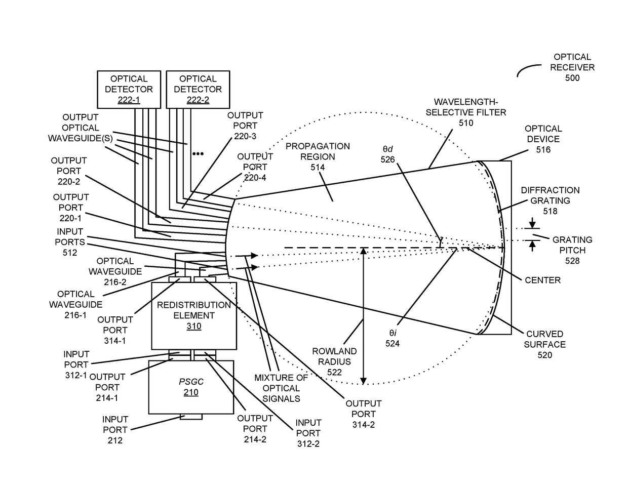
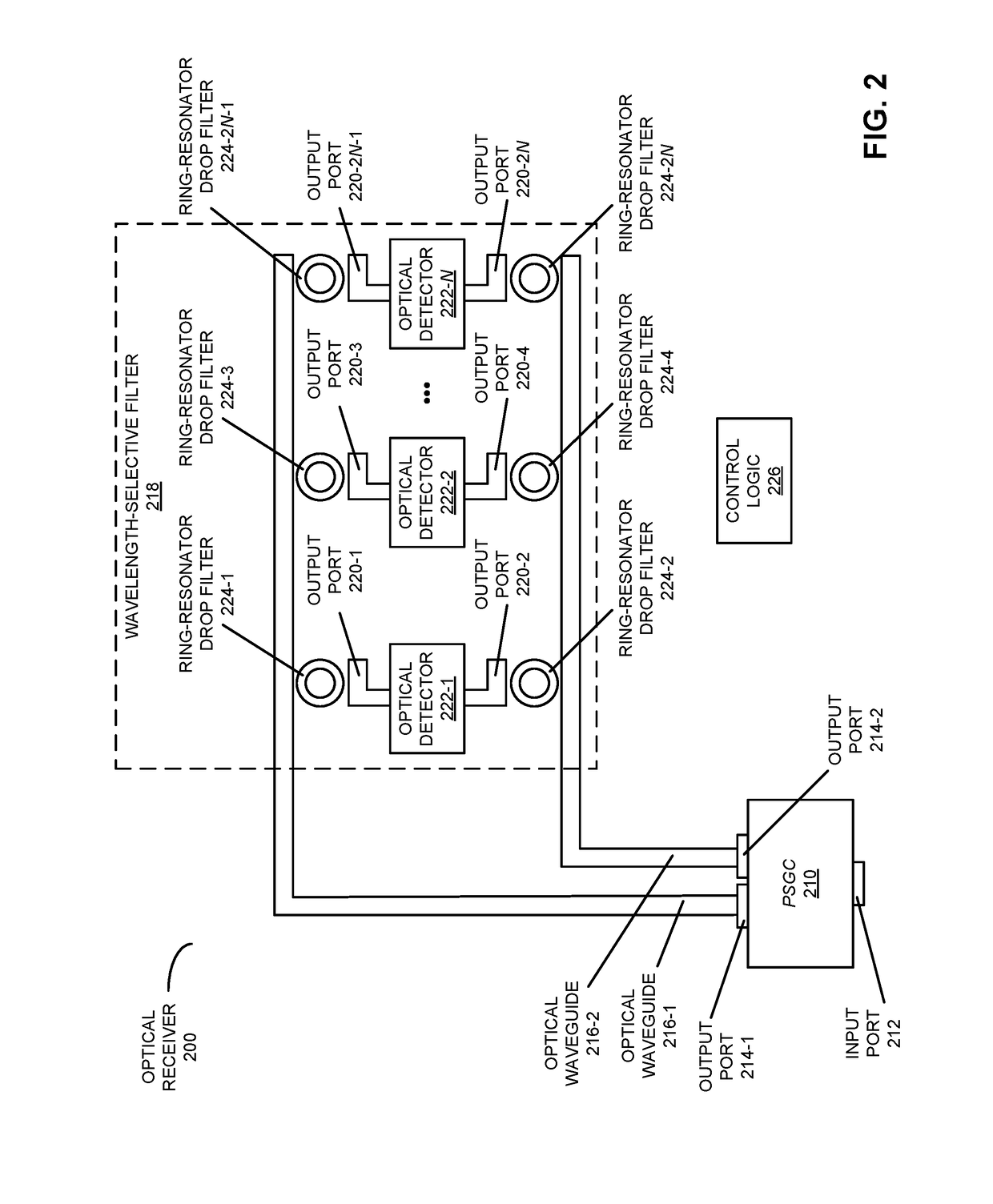
[0035]Embodiments of an optical receiver, a system that includes the optical receiver, and a method for providing output optical signals are described. Using silicon-photonic components that support a single polarization, the output of this optical receiver is independent of the polarization of an optical signal. In particular, using a polarization-diversity technique, the two orthogonal polarizations in a single-mode optical fiber are split in two and processed independently. For example, the two optical signals may be provided by a polarization-splitting grating coupler. Subsequently, a redistribution element provide mixtures of the two optical signals. Next, a wavelength channel in the two mixed optical signals is selected using a wavelength-selective filter (for example, using ring-resonator drop filters or an echelle grating) and converted into an electrical signal at an optical detector (such as a photodetector) to achieve polarization-independent operation.

[0036]By providing ...


PUM


Abstract

An optical receiver is described. Using silicon-photonic components that support a single polarization, the output of an optical receiver is independent of the polarization of an optical signal. In particular, using a polarization-diversity technique, the two orthogonal polarizations in a single-mode optical fiber are split in two and processed independently. For example, the two optical signals may be provided by a polarization-splitting grating coupler. Subsequently, a redistribution element provides mixtures of the two optical signals. Next, a wavelength channel in the two mixed optical signals is selected using a wavelength-selective filter (for example, using ring-resonator drop filters or an echelle grating) and converted into an electrical signal at an optical detector (such as a photodetector) to achieve polarization-independent operation.

Description

GOVERNMENT LICENSE RIGHTS[0001]This invention was made with United States government support under Agreement No. HR0011-08-9-0001 awarded by DARPA. The United States government has certain rights in the invention.BACKGROUND[0002]Field[0003]The present disclosure generally relates to a technique for locking an optical receiver to its received wavelength. More specifically, the present disclosure relates to a technique for locking an optical receiver that is insensitive to the polarization of an optical signal.[0004]Related Art[0005]Optical interconnects or links based on silicon photonics have the potential to alleviate inter-chip communication bottlenecks in high-performance computing systems that include multiple processor chips and memory chips. This is because, relative to electrical interconnects, optical interconnects offer significantly improved: bandwidth, density, power consumption, size, latency, and range. As a consequence, researchers are investigating optical interconnec...

Claims


Application Information

Patent Timeline
Patent Type & Authority Applications(United States)
IPC IPC(8): H04Q11/00H04J14/02H04J14/06
CPCH04Q11/0005H04J14/06H04Q2011/0009H04Q2011/0016H04J14/0212H04B10/671H04B10/675
Inventor LEE, DANIEL Y.ZHENG, XUEZHEKRISHNAMOORTHY, ASHOK V.
Owner ORACLE INT CORP
Why Eureka
Try Eureka