Low-latency low-uncertainty timer synchronization mechanism across multiple devices

a timer and multiple device technology, applied in the field of communication links, can solve the problems of high latency and high uncertainty, difficult and costly implementation of global synchronization, and difficulty in synchronizing devices

Active Publication Date: 2017-08-03
QUALCOMM INC
View PDF2 Cites 14 Cited by
  • Summary
  • Abstract
  • Description
  • Claims
  • Application Information

AI Technical Summary

Benefits of technology

[0020]In an aspect of the disclosure, a processor readable storage medium is disclosed. The storage medium may be a non-transitory storage medium and may store code that, when executed by one or more processors, causes the one or more processors to determining a first time value that corresponds to a future point in system time at a first device, transmitting a second time value from the first device to a second device through the data communication link, the second time value being incrementally greater than the first time value, transmitting a trigger signal fro

Problems solved by technology

For example, device synchronization can be problematic when, for example, RF devices are required to meet strict timing specifications in a multiple access RF network.
Implementing global synch

Method used


Image

  • Low-latency low-uncertainty timer synchronization mechanism across multiple devices
  • Low-latency low-uncertainty timer synchronization mechanism across multiple devices
  • Low-latency low-uncertainty timer synchronization mechanism across multiple devices

Examples


Embodiment Construction

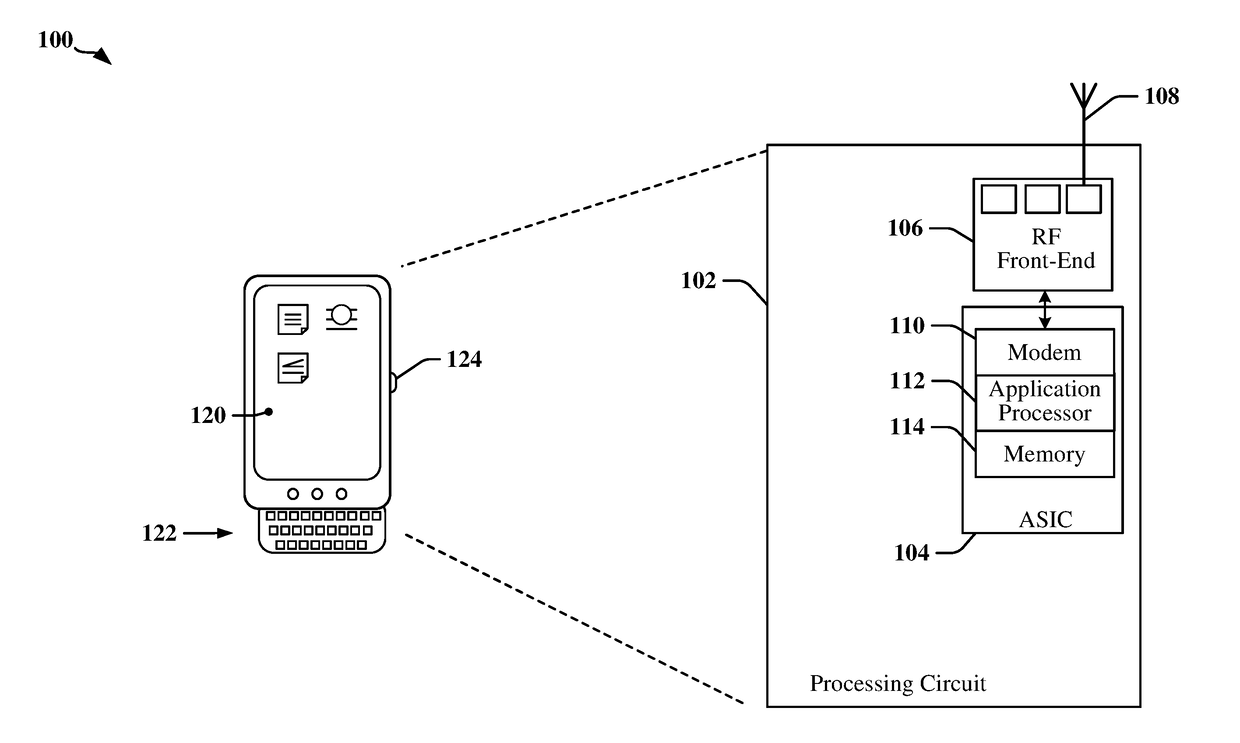
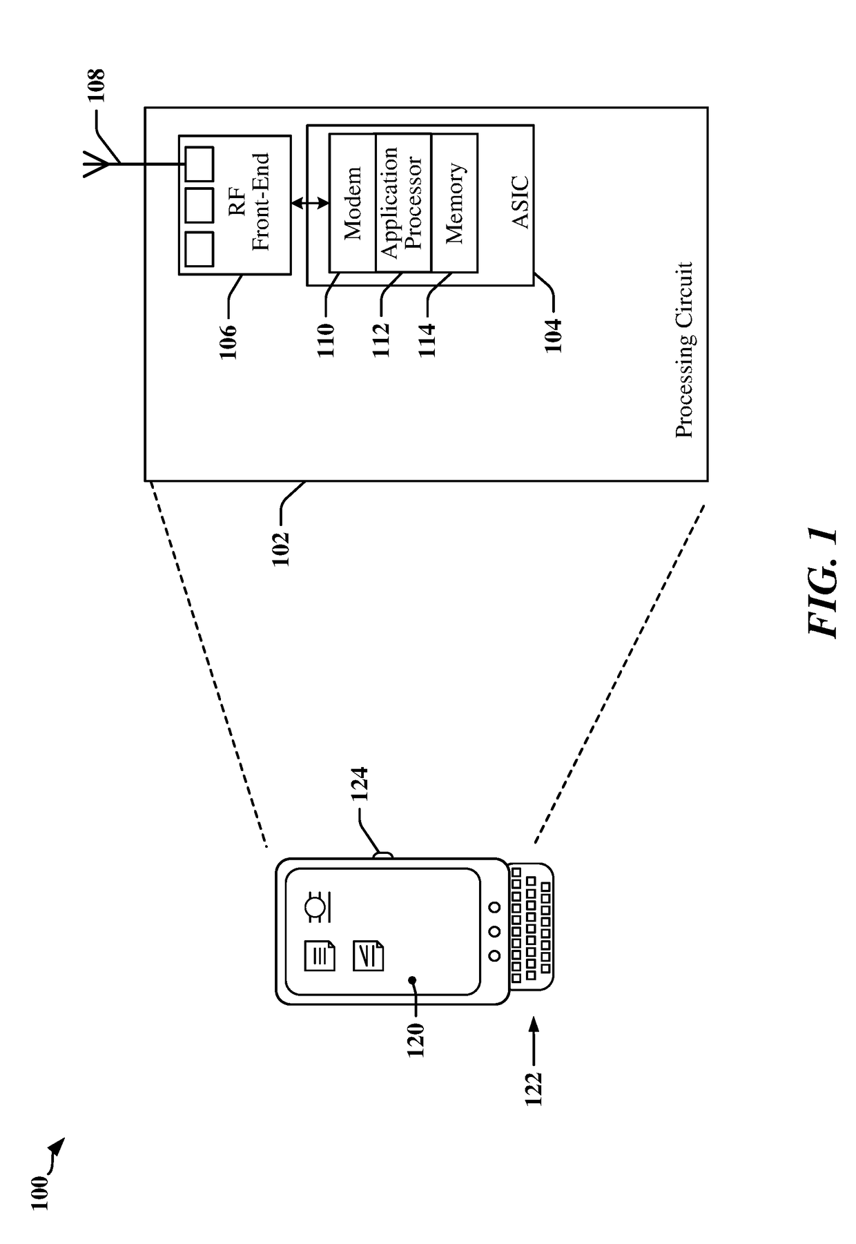
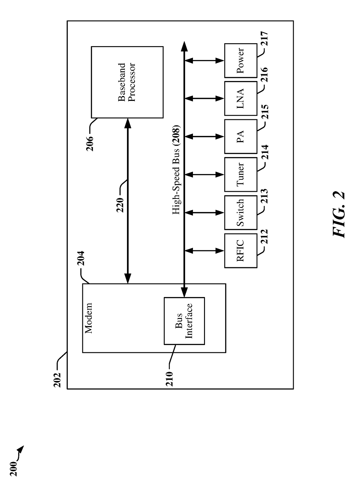
[0035]The detailed description set forth below in connection with the appended drawings is intended as a description of various configurations and is not intended to represent the only configurations in which the concepts described herein may be practiced. The detailed description includes specific details for the purpose of providing a thorough understanding of various concepts. However, it will be apparent to those skilled in the art that these concepts may be practiced without these specific details. In some instances, well-known structures and components are shown in block diagram form in order to avoid obscuring such concepts.

[0036]Several aspects of systems will now be presented with reference to various apparatus and methods. These apparatus and methods will be described in the following detailed description and illustrated in the accompanying drawings by various blocks, modules, components, circuits, steps, processes, algorithms, etc. (collectively referred to as “elements”)...


PUM


Abstract

Systems, methods, and apparatus for synchronizing timing in devices coupled to a data communication link are disclosed. In one example, a first device programs a future system time value in a second device. The first device launches a low-latency trigger signal that causes the future system time value to be loaded into a timer of the second device when a timer of the first device matches the future system time value. The second device measures phase difference between the trigger signal and edges of a clock signal used for timing in the second device. The phase difference is measured using an oversampling clock that provides a desired measurement reliability. The measured phase difference permits the first device to accurately determine system time as applied to the second device. The trigger signal can be provided on existing pins used by first and second devices in accordance with communication protocols and specifications.

Description

CROSS-REFERENCE TO RELATED APPLICATIONS[0001]This application claims the benefit of U.S. Provisional Application Ser. No. 62 / 290,309 filed in the U.S. Patent Office on Feb. 2, 2016, and from U.S. Provisional Application Ser. No. 62 / 358,429 filed in the U.S. Patent Office on Jul. 5, 2016, the entire content of these applications being incorporated herein by reference and for all applicable purposes.TECHNICAL FIELD[0002]The present disclosure relates generally to communications links connecting integrated circuit devices within an apparatus, and more particularly, to synchronization of timers in integrated circuit devices within an apparatus.BACKGROUND[0003]A mobile communications apparatus may include integrated circuit (IC) devices that use high-speed digital interconnects to communicate between or within certain IC devices. For example, a cellular telephone may include high-speed digital interconnects to support communication between radio frequency (RF) and baseband modem chipsets...

Claims


Application Information

Patent Timeline
IPC IPC(8): H04W56/00H04W52/02H04L7/02
CPCH04W56/001H04W52/0235H04L7/02G06F13/4273Y02D30/70
Inventor ROMERA, JOAQUINZETHNER, GRAIGKHAN, RAHEEL
Owner QUALCOMM INC
Why Eureka
Try Eureka