Grinding tool

a technology of grinding tool and polishing body, which is applied in the direction of metal-working apparatus, lapping machine, work carrier, etc., can solve the problems of difficult to perform highly accurate load control and difficult to properly measure the load, and achieve high-quality polishing processing, accurate measurement of the relative position of the polishing body, and expansion of the detection range of load

a technology of grinding tool and polishing body, which is applied in the direction of metal-working apparatus, lapping machine, work carrier, etc., can solve the problems of difficult to perform highly accurate load control and difficult to properly measure the load, and achieve high-quality polishing processing, accurate measurement of the relative position of the polishing body, and expansion of the detection range of load

US20170225288A1Active Publication Date: 2017-08-10TOSHIBA MASCH CO LTD

Image

  • Grinding tool
  • Grinding tool
  • Grinding tool

Examples


Embodiment Construction

[0022]Hereinafter, an embodiment of the invention will be described in detail with reference to the accompanying drawings.

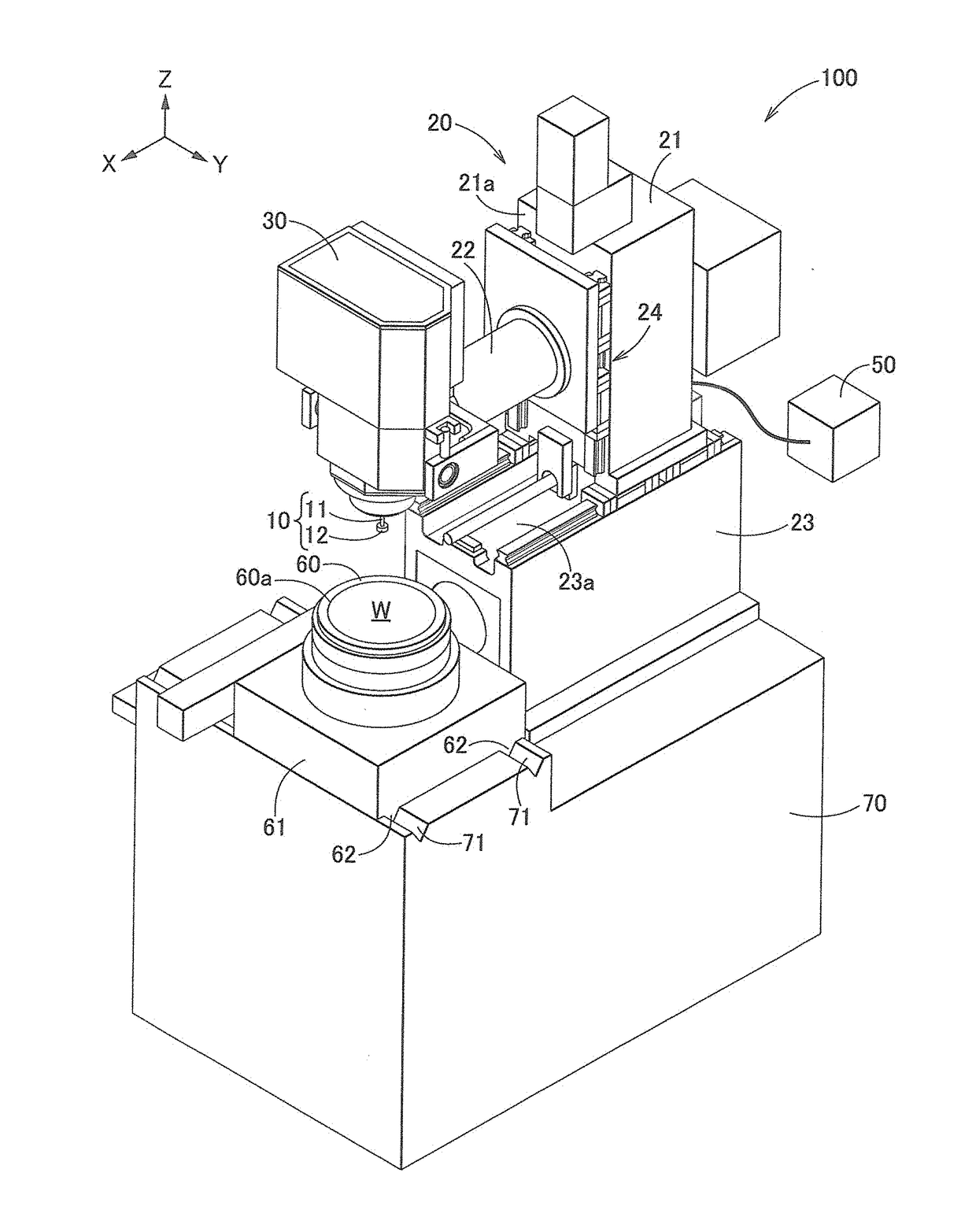
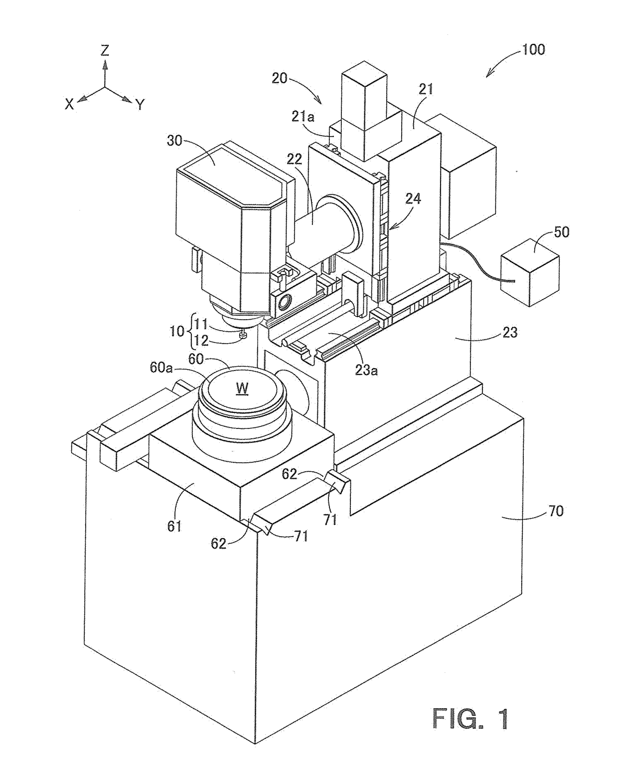
[0023]FIG. 1 is a schematic perspective view illustrating a polishing apparatus 100 according to an embodiment of the invention. As illustrated in FIG. 1, the polishing apparatus 100 according to this embodiment includes: a bed 70; a table 60 which is provided on the bed 70 and serves as a holding section that holds a material to be polished (wafer Wa); a polishing body 10 that polishes the material to be polished held by the table 60; a head 30 that supports the polishing body 10 via an elastic mechanism 32 (see FIG. 2); a driving mechanism 24 that causes the head 30 to be moved in a Z coordinate direction (up-and-down direction in FIG. 1) with respect to apparatus main body 20; and a control device 50, as a control unit, that is connected to the driving mechanism 24 and controls the driving mechanism 24.

[0024]Among them, the table (holding section) 60 is config...


PUM


Abstract

To provide a polishing apparatus capable of avoiding an overshoot with respect to a target load at the time of polishing, which is caused when position control is switched to load control in the polishing apparatus of a type where a polishing body is supported by a head via an elastic mechanism.A polishing apparatus includes: a holding section that holds a material to be polished; a polishing body that polishes the material to be polished held by the holding section; a head that supports the polishing body via an elastic mechanism; a driving mechanism that causes the head to be moved in a Z coordinate direction; a control unit that controls the driving mechanism; and a position sensor that measures a position of the polishing body with respect to the head. The load control is performed based on a measurement value of the position sensor and a spring constant value of the elastic mechanism.

Description

CROSS-REFERENCE TO RELATED APPLICATIONS[0001]This application is based upon and claims the benefit of priority from Japanese Patent Application No. 2016-021315, filed on Feb. 5, 2016 and Japanese Patent Application No. 2016-254137, filed on Dec. 27, 2016; the entire contents of which are incorporated herein by reference.BACKGROUND OF THE INVENTION[0002]Field of the Invention[0003]The present invention relates to a polishing apparatus.[0004]Background Art[0005]Conventionally, a polishing apparatus that uses a polishing pad, which is rotationally driven, as disclosed in WO 2013 / 038573, for example, has been known as a polishing apparatus that polishes a surface of a wafer made of a semiconductor material, and the like. In general, the polishing pad is provided at a distal end of a rotation shaft. The polishing pad including a rotation mechanism and a rotation shaft is supported by a head via an elastic mechanism. The head is supported by an apparatus main body via a driving mechanism....

Claims


Application Information

Patent Timeline
10 Aug 2017
Publication
US20170225288A1
IPC
B24B37/005; B24B37/30; B24B37/20
CPC
B24B37/005; B24B37/30; B24B37/20
Inventors
OMAGARI, HIROAKI; TOMIYASU, MASATERU