High Edge Cathodic Epoxy Electrocoat Composition

Active Publication Date: 2017-08-10
THE SHERWIN WILLIAMS HEADQUARTERS CO
View PDF4 Cites 1 Cited by
  • Summary
  • Abstract
  • Description
  • Claims
  • Application Information

AI Technical Summary

Benefits of technology

This patent describes an electrocoating composition that can be used to coat a variety of substrates. The composition includes an epoxy resin, an isocyanate-functional compound, and a silica-based additive. The resulting coating has several advantages over traditional coatings, including improved adhesion, durability, and corrosion resistance. The methods for applying this composition are also provided, ensuring proper coating of the substrate. Overall, this invention provides a more efficient and effective solution for coating surfaces.

Problems solved by technology

The use of coatings exhibiting good corrosion resistance prolongs the functionality and performance of the coating composition and the underlying substrate.
Components or parts in the heavy machinery industry, as well as in other industries, are often laser-cut, stamped or formed, and conventional coatings do not always coat the edges of such metal parts sufficiently to provide optimal corrosion resistance.
As a result, these components or parts suffer from edge corrosion and subsequent failure.

Method used


Image

  • High Edge Cathodic Epoxy Electrocoat Composition

Examples


example 1

Preparation of the Electrocoating Composition (Inventive Example)

[0062]The electrocoating composition used to form a coated article was prepared as a two-part system including a pigment paste part and a resin part. The pigment paste part was formed by mixing various components in the amounts shown in Table 1 to form an intermediary grind paste. The grind paste was mixed with a high speed dispenser and put through a media mill to disperse the solid material.

TABLE 1Grind paste componentAmount (wt %)Epoxy salt17.3104-A surfactant0.25Lactic Acid2.6DI Water41.3Tin catalyst3.04Dispersant3.02Carbon Black0.7Titanium Dioxide24.5Silica-based additive6.5Film forming agent0.8

[0063]After the grind paste was prepared, the pigment paste part of the composition was prepared by mixing the grind paste with solvent and deionized water. Table 2 lists the resulting component concentrations of the pigment paste part of the electrocoating composition.

TABLE 2Pigment paste componentsAmount (wt %)Epoxy salt1...

example 2

Preparation of the Electrocoating Composition (Comparative Example)

[0066]The electrocoating composition used to form the coated article of Example 2 was prepared as a two-part system in a similar manner to that discussed above for the coated article of Example 1. However, the grind paste prepared for the electrocoating composition for Example 2 did not include the silica-based additive. Thus, the resulting coating on the substrate for the coated article of Comparative Example A did not include the silica-based additive in the crosslinked matrix.

example 3

Corrosion Testing

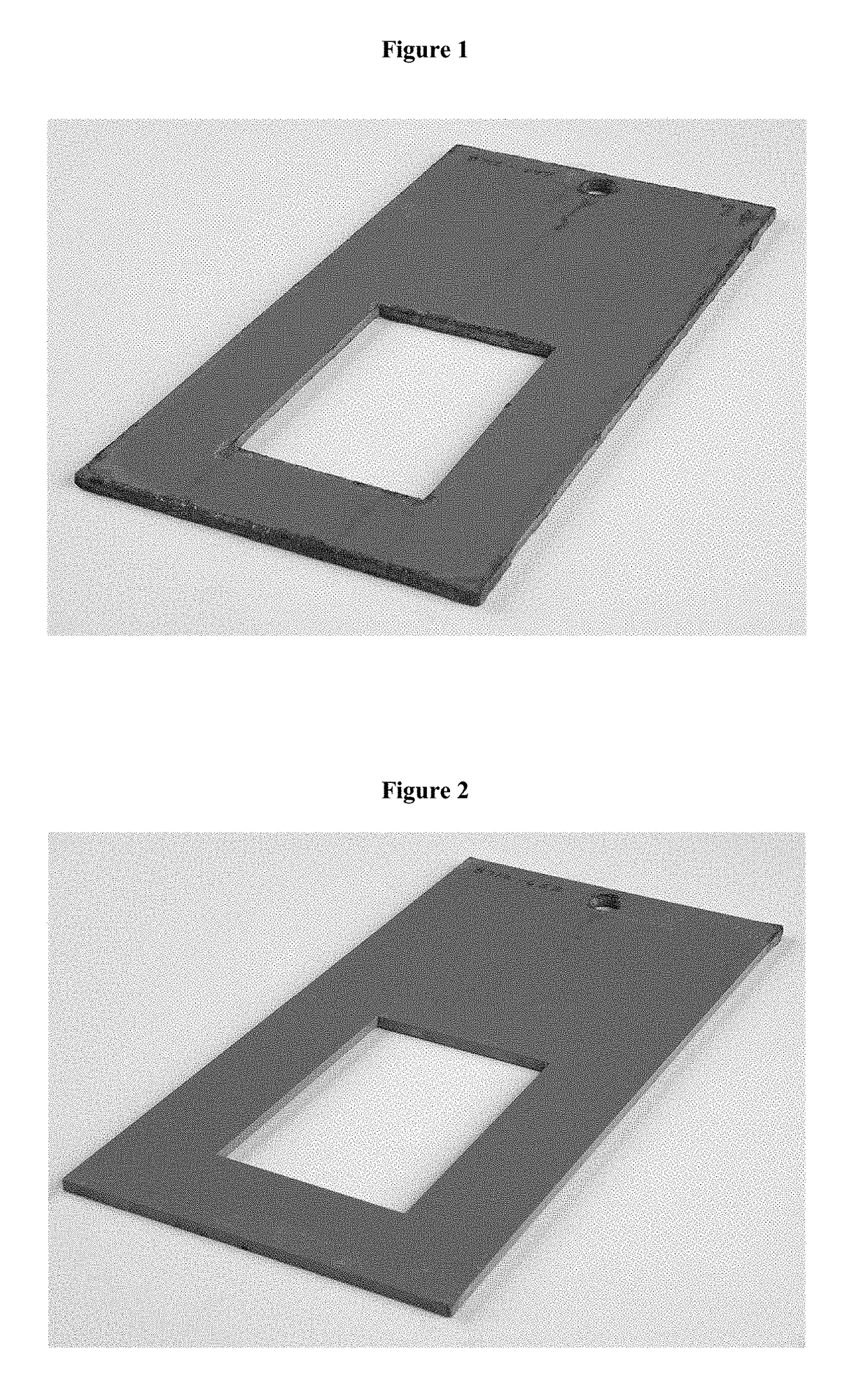
[0067]The corrosion resistance, specifically edge corrosion resistance, of the coated articles from Examples 1 and 2 was measured. Test panels made of cold rolled steel and measuring 4 in.×8 in. were prepared with a laser-cut insert. The panels were pretreated with iron phosphate and a deionized water rinse and then electrocoated with the inventive composition of Example 1 or the comparative composition of Example 2, according to the process described above. The corrosion resistance of the coatings was then assessed by exposing the panels to a corrosive environment according to the procedure described in the SAE J2334 cyclic corrosion test procedure. The extent of corrosion of each test panel is then measured.

[0068]As shown in FIG. 1, the coated article of Example 1 showed significantly less corrosion, including edge corrosion (only about 10% edge corrosion) relative to the coated article of Example 2 as shown in FIG. 2 (about 80% edge corrosion). Accordingly, the e...


PUM

PropertyMeasurementUnit
Fractionaaaaaaaaaa
Fractionaaaaaaaaaa
Fractionaaaaaaaaaa

Abstract

An electrocoating composition and a coating formed from the composition are described herein. The electrocoating composition includes at least an epoxy resin component, an isocyanate-functional component and a silica-based additive. The coating shows about 40 to 70% reduction in edge corrosion relative to a conventional coating.

Description

CROSS-REFERENCE TO RELATED APPLICATIONS[0001]This application is a continuation of International Application No. PCT / US2015 / 057493 filed Oct. 27, 2015, which claims priority from U.S. Provisional Application Ser. No. 62 / 073,367, filed Oct. 31, 2014, each of which is incorporated herein by reference in its entirety.BACKGROUND OF THE INVENTION[0002]Coatings are typically applied to substrates to provide protective and / or decorative qualities. One effective technique for applying coatings includes an electrocoating process, which typically involves depositing a composition onto an electrically conductive substrate with an applied electrical potential. Early attempts at commercial electrocoating processes used anionic electrocoating processes, where the substrate being coated served as the anode. However, cathodic or cationic electrocoating processes have become increasingly popular, and today, are the most prevalent methods of electrocoating.[0003]One desired property of coatings is co...

Claims


Application Information

Patent Timeline
IPC IPC(8): C25D13/04C09D163/00C25D13/22C09D5/44
CPCC25D13/04C09D5/4434C08K3/36C25D13/22C09D163/00C09D5/08C09D5/443C09D5/4453C08G18/643C08G18/80C08G18/242C09D175/04C08G2150/90
Inventor TERSTEEG, JILL
Owner THE SHERWIN WILLIAMS HEADQUARTERS CO
Why Eureka
Try Eureka