Drive device and control method for drive device

a technology of a drive device and a control method, which is applied in the direction of electronic commutators, dynamo-electric gear control, and dynamo-electric converter control, etc., can solve the problems of affecting the operation of the motor, the torque ripple of the motor may not be sufficiently suppressed, and the phenomenon is likely to occur, so as to suppress the torque ripple of the motor and the effect of reducing the vibration of the motor and noise, more sufficiently suppressing the torque rippl

Active Publication Date: 2017-08-10
AISIN AW CO LTD +1
View PDF3 Cites 8 Cited by
  • Summary
  • Abstract
  • Description
  • Claims
  • Application Information

AI Technical Summary

Benefits of technology

[0009]The drive device of the disclosure includes an electronic control unit which detects the electric angle of the motor and the rotation speed of the motor. Then, when the rotation speed of the motor detected by the electronic control unit is high, the electric angle compensation amount for compensating for deviation between the actual electric angle of the motor when the control signal is output to the inverter and the actual electric angle of the motor when the torque of the motor changes is set to be larger than that when the rotation speed is low, the electric angle for compensation is set using the electric angle of the motor detected by the electronic control unit and the electric angle compensation amount. The corrected torque is set by correcting the required torque required for the motor based on the electric angle for compensation such that the torque ripple of the motor is cancelled, and the inverter is controlled such that the corrected torque is output from the motor. When the rotation speed of the motor is high (the frequency of the torque ripple of the motor is high), deviation between the electric angle detected by the electronic control unit and the actual electric angle of the motor when the actual torque (current) of the motor changes according to switching of a plurality of switching elements of the inverter becomes larger than that when the rotation speed of the motor is low (the frequency of the torque ripple of the motor is low). Accordingly, when the rotation speed of the motor is high, the electric angle compensation amount is set to be larger than that when the rotation speed of the motor is low, and control is performed based on the required torque and the electric angle for compensation according to the electric angle detected by the electronic control unit and the electric angle compensation amount such that torque (corrected torque) with the torque ripple of the motor cancelled from the required torque is output from the motor, whereby it is possible to more sufficiently suppress the torque ripple of the motor. As a result, it is possible to more sufficiently suppress vibration of the motor and noise.
[0010]The electronic control unit may be configured to vi) set a basic current command of a d-axis based on the required torque, vii) set a basic current command of a q-axis based on the required torque, viii) set a correction coefficient for cancelling the torque ripple based on the required torque and the electric angle for compensation, ix) set a current command of the d-axis by multiplying the basic current command of the d-axis by the correction coefficient, x) set a current command of the q-axis by multiplying the basic current command of the q-axis by the correction coefficient, and xi) control the inverter using the current command of the d-axis and the current command of the q-axis. In this case, the current command of the d-axis and the current command of the q-axis are set using the correction coefficient based on the electric angle for compensation, whereby it is possible to more sufficiently suppress the torque ripple of the motor.
[0011]The electronic control unit may be configured to xii) set a feedback term of the d-axis based on the current command of the d-axis and a current of the d-axis, xiii) set a feedforward term of the d-axis based on the electric angle for compensation, the required torque, and the rotation speed of the motor, xiv) set a voltage command of the d-axis using the feedforward term of the d-axis and the feedback term of the d-axis, xv) set a feedback term of the q-axis based on the current command of the q-axis and a current of the q-axis, xvi) set a feedforward term of the q-axis based on the electric angle for compensation, the required torque, and the rotation speed of the motor, xvii) set a voltage command of the q-axis using the feedforward term of the q-axis and the feedback term of the q-axis, and xviii) control the inverter using the voltage command of the d-axis and the voltage command of the q-axis. In this case, with the use of the feedforward term of the d-axis and the feedforward term of the q-axis according to the electric angle for compensation, the required torque, and the rotation speed are used, whereby it is possible to more sufficiently suppress the torque ripple of the motor.

Problems solved by technology

Accordingly, if the sine signal and the torque ripple suppression signal are calculated using the magnetic pole phase of the motor as it is, the torque ripple of the motor may not be sufficiently suppressed.
In particular, if the torque ripple of the motor becomes a high frequency, such a phenomenon is likely to occur.

Method used


Image

  • Drive device and control method for drive device
  • Drive device and control method for drive device
  • Drive device and control method for drive device

Examples


Embodiment Construction

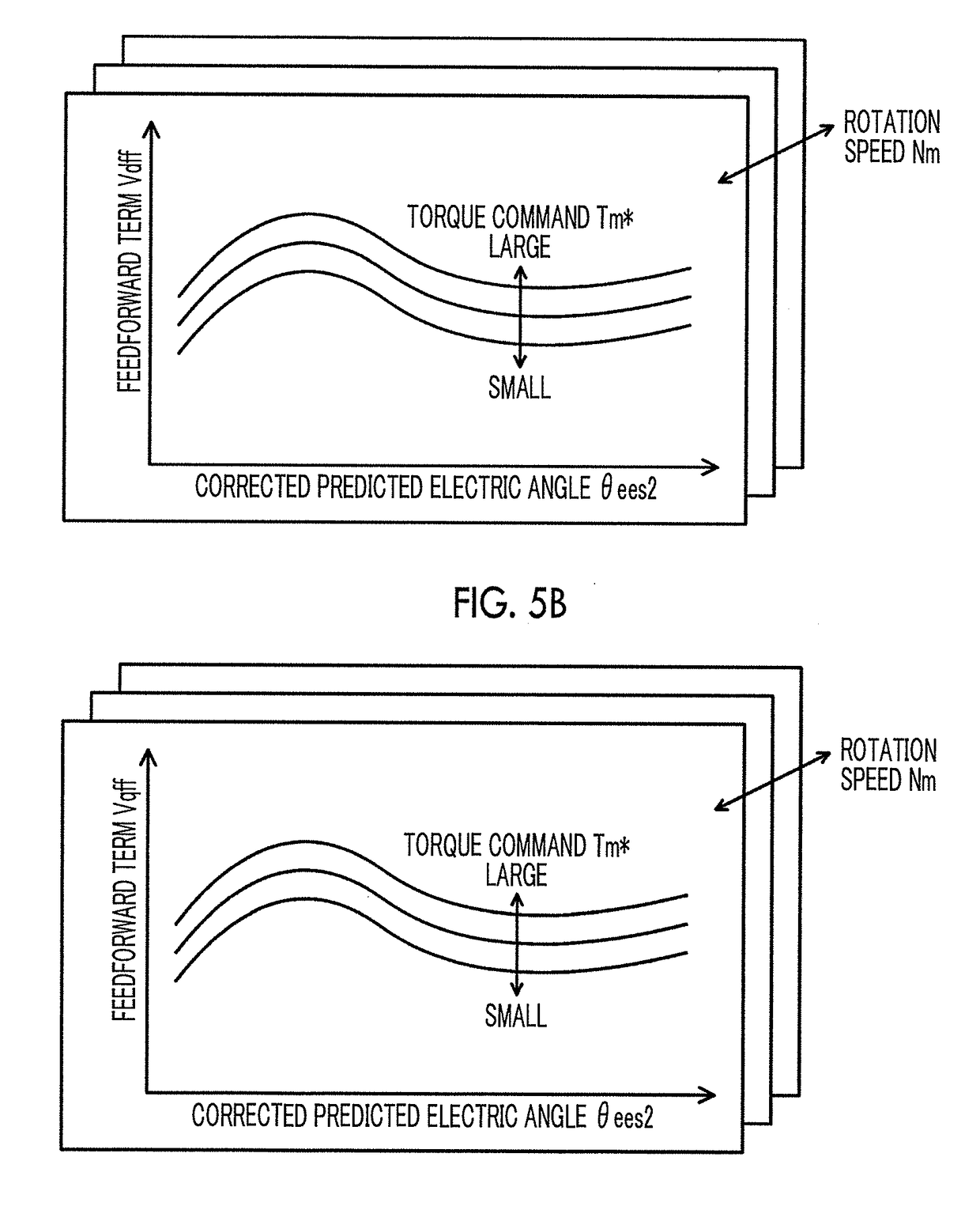
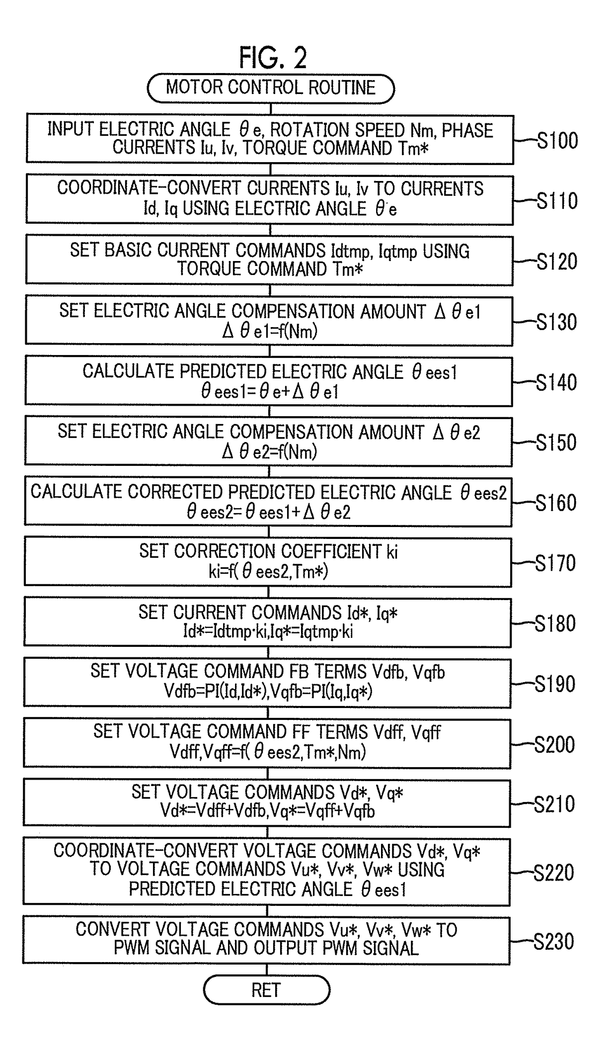
[0018]Next, a mode for carrying out the disclosure will be described using an example.

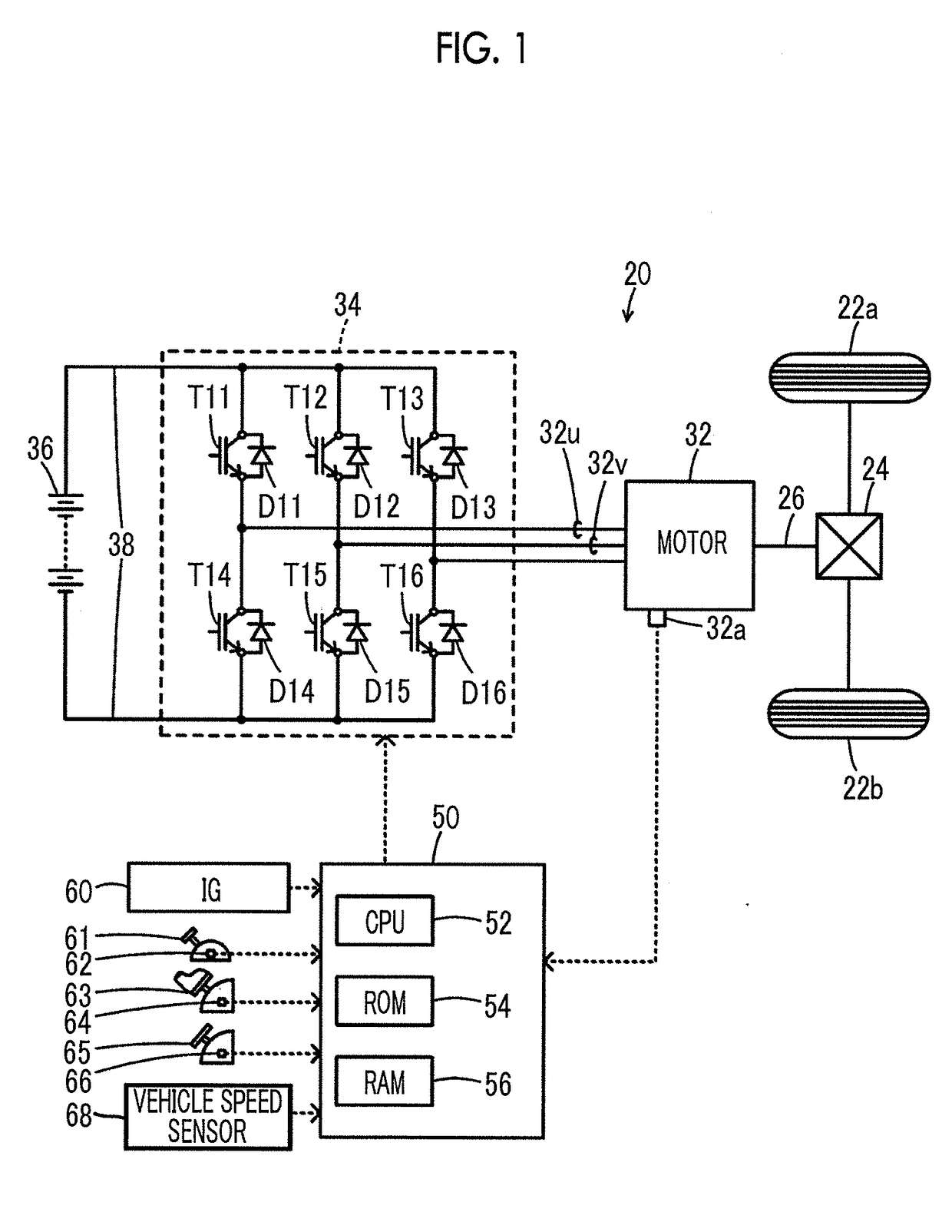
[0019]FIG. 1 is a configuration diagram showing the outline of the configuration of an electric vehicle 20 in which a drive device as an example of the disclosure is mounted. As shown in FIG. 1, the electric vehicle 20 of the example includes a motor 32, an inverter 34, a battery 36, and an electronic control unit (ECU) 50.

[0020]The motor 32 is constituted as, for example, a synchronous motor generator, and a rotor is connected to a drive shaft 26 coupled to drive wheels 22a, 22b through a differential gear 24. The inverter 34 is connected to the motor 32 and is connected to the battery 36 through a power line 38. The inverter 34 has six transistors (switching element) T11 to T16 and six diodes D11 to D16. The transistors T11 to T16 are arranged in pairs of two so as to become a source side and a sink side with respect to a positive electrode line and a negative of the power line 38. The six diodes...


PUM


Abstract

Basic current commands of a d-axis and a q-axis are set based on a torque command of a motor. Subsequently, when the rotation speed of the motor is high, an electric angle compensation amount is set to be larger than that when the rotation speed of the motor is low, and a corrected predicted electric angle is set by adding the electric angle compensation amount to a predicted electric angle predicted from an electric angle based on a rotation position of a rotor of the motor from a rotation position detection sensor. Then, current commands of the d-axis and the q-axis are set by multiplying the basic current commands of the d-axis and the q-axis by a correction coefficient based on the corrected predicted electric angle, and an inverter is controlled using the current commands.

Description

CROSS-REFERENCE TO RELATED APPLICATIONS[0001]This application claims priority to Japanese Patent Application No. 2016-020841 filed on Feb. 5, 2016, the entire contents of which are hereby incorporated by reference.BACKGROUND[0002]1. Technical Field[0003]The present disclosure relates to a drive device and a control method for a drive device.[0004]2. Description of Related Art[0005]Hitherto, as this kind of drive device, a drive device including a motor, an inverter configured to drive the motor, a magnetic pole phase detector configured to detect a magnetic pole phase of the motor, and a control device configured to control the inverter is suggested (for example, see Japanese Patent Application Publication No. 2002-223582 (JP 2002-223582 A)). The control device calculates the magnitude of a torque ripple generated in output torque of the motor according to the magnitude of a torque command of the motor to create a torque ripple amplitude signal, calculates a sine signal according to...

Claims


Application Information

Patent Timeline
Patent Type & Authority Applications(United States)
IPC IPC(8): H02P6/15H02P6/10H02P21/20
CPCH02P6/153H02P6/10H02P21/20B60L15/025H02P21/05H02P21/06B60L2240/423Y02T10/64
Inventor SATO, RYOJITANAKA, SHOGOSHIMAJI, TAKUYA
Owner AISIN AW CO LTD
Why Eureka
Try Eureka