Spinal Fusion Apparatus

a technology of spinal fusion and apparatus, which is applied in the field of orthopedic surgery and neurosurgery, can solve the problems of spinal deformities, inadequate lordosis, and the technique of anterior-posterior fusion and posterior alone operations can be predisposed to flat back deformities, so as to minimize the height, minimize the height, and maximize the anterior height

Active Publication Date: 2017-08-17
KRAEMER PAUL E
View PDF8 Cites 3 Cited by
  • Summary
  • Abstract
  • Description
  • Claims
  • Application Information

AI Technical Summary

Benefits of technology

[0010]It would therefore be desirable to provide an implant, such as for use in TLIF procedures, that maximizes anterior height (e.g., that maximizes the height of the anterior-most portion of the vertebral body, the anterior column), minimizes posterior height (e.g., that minimizes the height of the posterior-most portion of the vertebral body, the middle column), avoids point loading during insertion, inserts with minimal risk of neurologic trauma or damage to end plate bone, facilitates a posterior approach, achieves lordosis (e.g., up to about 30 degrees) even absent ideal placement and / or about non-orthogonal axes, and freely allows lordosis to increase after implantation and until the vertebral segment is ultimately fixed in place, usually through posterior instrumentation (e.g., pedicle screw / rod systems).
[0015]Also disclosed herein is an interbody spinal fusion cage configured to achieve lordosis when placed posteriorly, including: a superior member including an anterior end, a posterior end, a superior bearing surface extending between the anterior end of the superior member and the posterior end of the superior member, and a superior joint component between the anterior end of the superior member and the posterior end of the superior member; and an inferior member including an anterior end, a posterior end, an inferior bearing surface extending between the anterior end of the inferior member and the posterior end of the inferior member, and an inferior joint component between the anterior end of the inferior member and the posterior end of the inferior member, wherein the superior joint component is attached to the inferior joint component in a manner that allows the interbody spinal fusion cage to achieve lordosis even if implanted non-orthogonal to the sagittal plane.

Problems solved by technology

Indeed, in many practices, spinal deformities often result from previous spinal operations where inadequate lordosis was achieved.
Techniques such as anterior-posterior fusions and posterior alone operations can be predisposed to flatback deformities, in part because of the inability to control anterior and posterior columns simultaneously.
Growing literature links these concepts to increases in adjacent segment stresses, degeneration, and revision operations, with attendant patient suffering and costs to the health care system.
Flatback deformity can lead to increased back pain, accelerated adjacent level changes, and repeat surgery.
One of the challenges attendant to a TLIF procedure is obtaining optimum increase in the height of the anterior column while achieving adequate posterior disc shortening.
Jackson's device, however, requires a more complex, and therefore more invasive, anterior approach.
Moreover, Jackson's implant is not freely mobile; to change the amount of lordosis, the practitioner must manipulate a screw, again from an anterior approach; Jackson's device is not operable without the screw.
In addition, Jackson's implant is limited to an orthogonal axis of lordosis (e.g., it can only achieve lordosis about an axis that is perpendicular to the long axis of the implant).
Such devices can, however, result in increased disc height without increased lordosis, potentially due to the blocking of the posterior aspect of the vertebral body.
These devices can be hindered by a learning curve, a lack of ideal bone graft placement, the requirement for a very complete discectomy, and diminished lordosis (relative to pre-procedure) if the device does not track as desired.
Such devices, however, result in point loading during rotation (e.g., when at 45 degrees), which can cause damage to the soft endplate bone and ultimate cavitation of the bone around the graft.

Method used


Image

  • Spinal Fusion Apparatus
  • Spinal Fusion Apparatus
  • Spinal Fusion Apparatus

Examples


Embodiment Construction

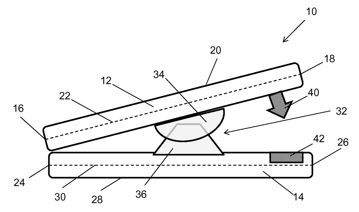
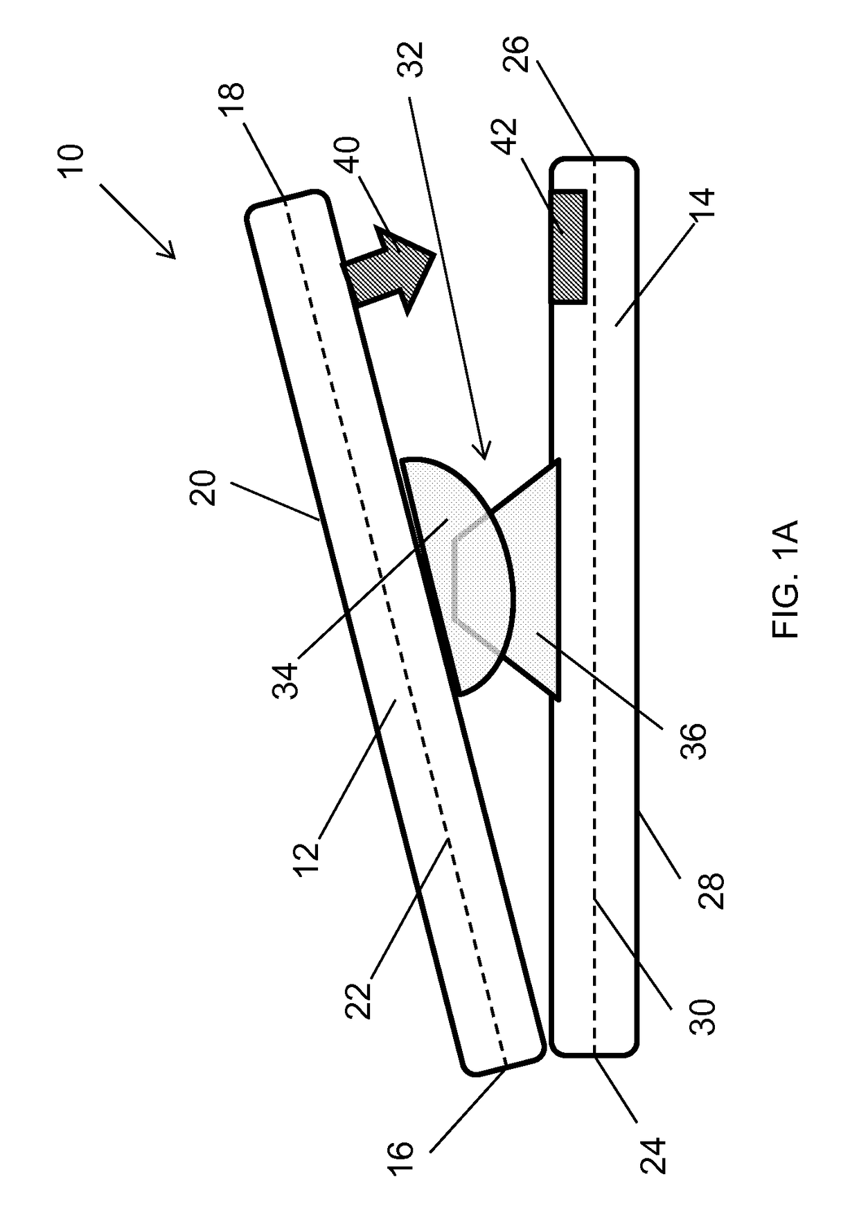
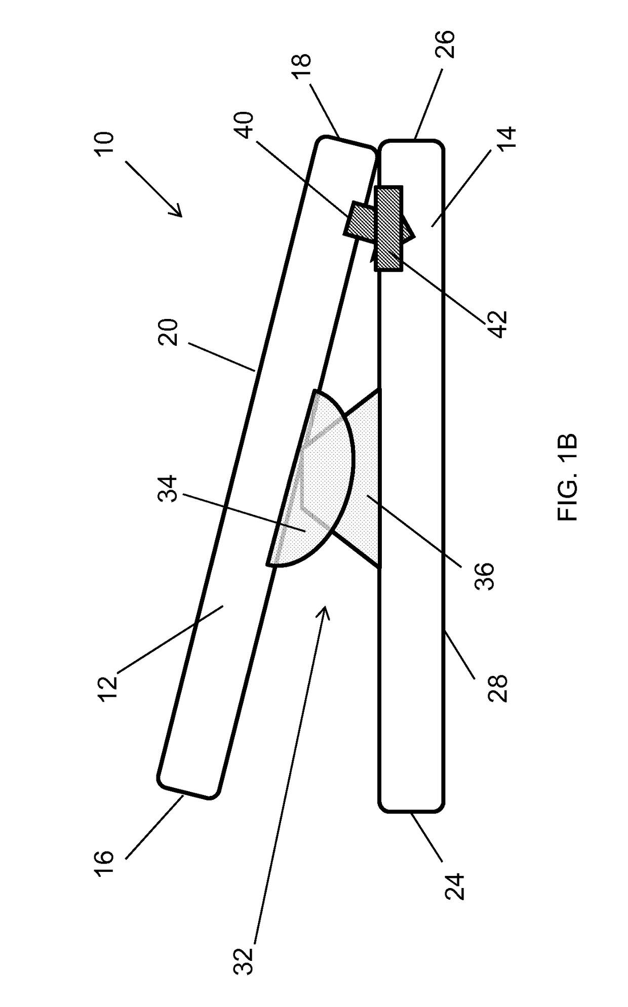
[0034]FIG. 1 is a schematic side view of an interbody spinal fusion cage 10 according to aspects of the instant disclosure. As will be discussed in detail below, interbody spinal fusion cage 10 is configured such that it will achieve lordosis when placed between two vertebrae via a posterior approach.

[0035]Interbody spinal fusion cage 10 includes a superior member 12 and an inferior member 14. Superior member 12 includes an anterior end 16, a posterior end 18, and a superior bearing surface 20 that extends along an axis 22 (shown in dashed line) between anterior end 16 and posterior end 18. Similarly, inferior member 14 includes an anterior end 24, a posterior end 26, and an inferior bearing surface 28 that extends along an axis 30 (shown in dashed line) between anterior end 24 and posterior end 26.

[0036]Superior member 12 and anterior member 14 are interconnected via a joint 32. As illustrated to good advantage in FIG. 1, joint 32 is connected to superior member 12 at a first point...


PUM


Abstract

An interbody spinal fusion cage for posterior interbody fusion procedures includes a superior member and an inferior member connected to each other via a joint. The joint allows the interbody spinal fusion cage to achieve lordosis even if implanted non-orthogonal to the sagittal plane. For example, the joint can be a hinge oriented non-normal to a longitudinal axis of the interbody spinal fusion cage, a polyaxial ball joint, and / or a universal joint. Complementary locking mechanisms, such as locking teeth or a ratchet-and-pawl arrangement, can be provided near the posterior ends of the superior and inferior members in order to prohibit the posterior ends of the superior and inferior members from separating from each other in situ. Bone holes can be provided in the superior and inferior members.

Description

CROSS-REFERENCE TO RELATED APPLICATIONS[0001]This application claims the benefit of U.S. provisional application Nos. 62 / 036,263, filed 12 Aug. 2014; 62 / 045,958, filed 4 Sep. 2014; 62 / 102,911, filed 13 Jan. 2015; and 62 / 105,833, filed 21 Jan. 2015. Each of the foregoing provisional applications is hereby incorporated by reference as though fully set forth herein.BACKGROUND[0002]The instant disclosure relates to orthopedic surgery and neurosurgery. In particular, the instant disclosure relates to devices and methods for posterior interbody fusion procedures, including, without limitation, transforaminal lumbar interbody fusion (“TLIF”) and posterior lumbar interbody fusion (“PLIF”) procedures.[0003]Sagittal balance and spinopelvic harmony have become prevalent concepts in spinal deformity over the past several years. Although there is no clear consensus, these concepts also apply to degenerative spinal surgery. Indeed, in many practices, spinal deformities often result from previous ...

Claims


Application Information

Patent Timeline
Patent Type & Authority Applications(United States)
IPC IPC(8): A61F2/44
CPCA61F2/4455A61F2/4425A61F2002/30471A61F2002/30489A61F2002/30649A61F2002/30518A61F2002/3054A61F2002/30772A61F2002/30522A61F2002/30528A61F2002/30476A61F2002/30477A61F2002/30538A61F2002/30487
Inventor KRAEMER, PAUL E.
Owner KRAEMER PAUL E
Why Eureka
Try Eureka