Microwave frequency magnetic field manipulation systems and methods and associated application instruments, apparatus and system

a technology of microwave frequency and magnetic field, applied in the field of microwave frequency magnetic field manipulation systems and methods as, can solve problems such as challenging tasks in achieving operation in such a regime, and achieve the effect of high magnetic field strength

Active Publication Date: 2017-08-17
UNIV OF WESTERN AUSTRALIA
View PDF1 Cites 12 Cited by
  • Summary
  • Abstract
  • Description
  • Claims
  • Application Information

AI Technical Summary

Benefits of technology

[0007]one or more signal sources coupled to the cavity for supplying microwave signals to facilitate the generation of electric fields in the gaps and associated magnetic fields in opposite direction about two mutually adjacent posts such that the magnetic fields reinforce each other in a focusing region between the two mutually adjacent posts.
[0071]In a tenth aspect there is disclosed a re-entrant microwave cavity resonator comprising a substantially continuous and closed internal surface with at least two opposed sides, and at least two posts which are in physical contact with a first of the two opposed sides and extend toward a second of the two opposed sides the posts being dimensioned or positionable to form or selectively enable the formation of respective gaps between free ends posts and the second of the two opposed; and a tuning system arranged to enable variation of a size of the gaps. This may include varying the gap size so that it can be closed to zero and thereby short circuit a post across the opposite sides of the internal surface of the cavity.

Problems solved by technology

Achieving operation in such a regime is a challenging task, because one usually encounters contradictory requirements for the coupling of a system to its environment.

Method used


Image

  • Microwave frequency magnetic field manipulation systems and methods and associated application instruments, apparatus and system
  • Microwave frequency magnetic field manipulation systems and methods and associated application instruments, apparatus and system
  • Microwave frequency magnetic field manipulation systems and methods and associated application instruments, apparatus and system

Examples


Embodiment Construction

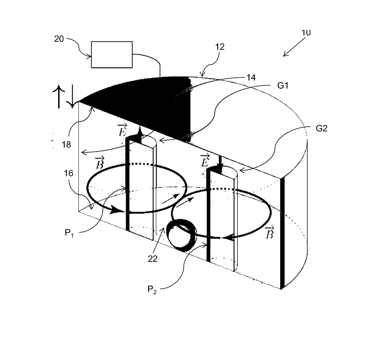
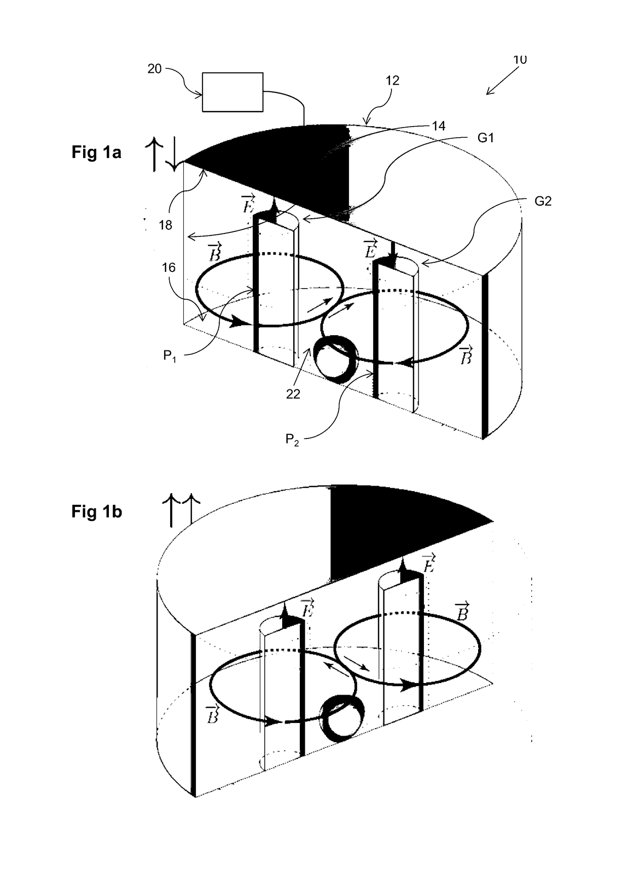
[0099]FIG. 1a is a schematic representation of a basic embodiment of the disclosed microwave frequency magnetic field manipulation system 10 (hereinafter referred to in general as “system 10”). The system 10 comprises a re-entrant microwave cavity 12 having a substantially continuous and closed internal surface 14 with at least two opposite sides 16 and 18. Two posts, P1 and P2 (hereinafter referred to in general as “posts P”) are provided in the cavity 12. The posts P1 and P2 are in physical and more particularly electrical contact with one of the sides 16. The electrical contact is a short circuit. The posts P extend toward but terminate short of the opposite side 18. This leaves or produces respective gaps G1 and G2 (hereinafter referred to in general as “gaps G”) between free ends of the posts P and the side 18. The system 10 also has a signal source 20 coupled to the cavity 12 for supplying microwaves. The source 20 is depicted here as a single source. However the source 20 may...


PUM


Abstract

A microwave frequency magnetic field manipulation system (10) comprises a re-entrant microwave cavity (12) having a substantially continuous and closed internal surface (14) with at least two opposite sides (16 and 18). Two or more posts, P1, P2, . . . Pn (hereinafter referred to in general as “posts P”) are provided in the cavity (12). The posts P are in physical and more particularly electrical contact with one of the sides 16. Respective gaps G atre or can be formed between free ends of the posts P and the side (18). The system (10) also has a signal source (20) coupled to the cavity (12) for supplying microwaves. The source (20) supplies microwave signals at frequencies that facilitate the generation of magnetic fields in opposite directions about at least two mutually adjacent posts P. Accordingly the magnetic field is reinforced in a common region (22) between the mutually adjacent posts P.

Description

TECHNICAL FIELD[0001]The present disclosure is in relation to microwave frequency magnetic field manipulation systems and methods as well as instruments, apparatus and systems and associated application instruments, methods and systems.BACKGROUND[0002]The disclosed systems and methods have their genesis in the field of quantum information. Ongoing development of devices and experimental techniques that utilise the quantum nature of matter to perform storage, transfer and processing of quantum information is critical to achieve the ambitious goal of workable quantum computation. The mainstream framework used to reach this goal is known as quantum electro dynamics (QED). Under this framework, a high-fidelity technology must be able to exchange information with preserved coherence, i.e. to demonstrate the so called strong coupling regime, in order to be useful for any quantum application. This situation is characterised by a coupling between two subsystems that is stronger than the mea...

Claims


Application Information

Patent Timeline
Patent Type & Authority Applications(United States)
IPC IPC(8): H01P7/06H03H9/54H05K7/20H03H9/17
CPCH01P7/06H05K7/20H03H9/54H03H9/17H01P1/2053
Inventor TOBAR, MICHAEL EDMUNDGORYACHEV, MAXIM
Owner UNIV OF WESTERN AUSTRALIA
Why Eureka
Try Eureka