System and method for power transfer

a power transfer and system technology, applied in the direction of electric power, transportation and packaging, electric vehicles, etc., can solve the problems of unsatisfactory approach, unreliable power supply, and unreliable power supply, so as to reduce the induced current in the windings and reduce the induced current in the transmitter coils

Active Publication Date: 2017-08-17
APPLE INC
View PDF2 Cites 72 Cited by
  • Summary
  • Abstract
  • Description
  • Claims
  • Application Information

AI Technical Summary

Benefits of technology

[0050]A slug formed of a magnetically permeable material may extend sufficiently above each coil to substantially reduce induced currents in the windings. The slug may project about the height of each winding above the top of each winding or about or above 1 mm above the top of each winding. Four common openings may be defined within each transmitter coil to accommodate the slugs. An air gap may be provided between each transmitter coil and each slug to reduce induced currents in the transmitter coils.

Problems solved by technology

A problem associated with charging mat design is ensuring that the inductive power transfer is adequately efficient.
However, this approach is not ideal since it requires the user to place their device carefully onto the charging mat.
Another problem associated with charging mat design is enabling multiple devices to be charged simultaneously in an efficient and cost effective manner.
However, the magnetic field produced by a large transmitting coil may not be uniform, with ‘weak spots’ towards the centre of the charging mat.
Further, since the entire surface is being ‘powered’ it is possible that any portions of the surface not covered by a device being charged may be a safety hazard.
Though this allows more freedom in terms of where a user may place a device, like the single coil design, the boundary between adjacent transmitting coils can result in weak spots due to the cancelling effects of adjacent coils whereby receivers do not receiver sufficient power.
A further problem arises when a non-receiver is brought into the range of the transmitter, and an unwanted current (and therefore heat) is induced therein.
Attempting to transfer power to non-compatible receivers may result in inefficient power transfer (thus, undesired energy loss), or transmitter and / or receiver failure.
Though this provides a means for controlling when the transmitter should be powered, it undermines the convenience that is a goal of many IPT systems.
It also requires a user to manually switch off the transmitter when the receiver is removed and does not accommodate any parasitic loads that may be introduced into the vicinity of the transmitter without the user's knowledge.

Method used


Image

  • System and method for power transfer
  • System and method for power transfer
  • System and method for power transfer

Examples


Embodiment Construction

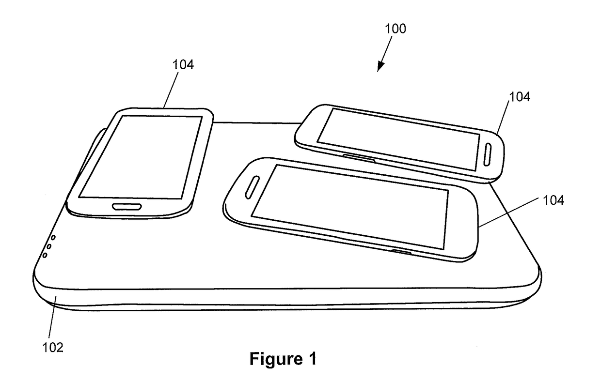
[0097]FIG. 1 illustrates a typical application 100 of the present invention. The wireless power transfer system 100 is illustrated as having a transmitter or charging “pad”102 having a plurality of consumer electronic devices 104 disposed thereon so that electrical loads or energy storage elements, e.g., batteries, of the devices can be charged with electrical power in a wireless or contactless manner. In the illustrated example, the electrical power is provided between the pad and devices via electromagnetic induction or inductive power transfer (IPT) using loose-coupling techniques between transmitter and receiver electronics. However, other types of wireless power transfer may be possible for such a system, such as capacitive power transfer.

[0098]The transmitter and receiver electronics of the charging pad 102 and the devices 104 are configured so that the disposition of the devices on the pad can be arbitrarily selected by the user without the need to ensure pre-defined alignmen...


PUM


Abstract

A system for inductive power transfer that may selectively transmit power in a plurality of modes based on characteristics of a power receiver and determine which transmitter coils to drive based on received signal strength information. The inductive power transfer transmitter may detect characteristics of the power receiver in order to control the mode of the power transfer and selectively control which transmitter coils are driven based on signal strength information received from a power receiver. The power transmitter may have slugs formed of a magnetically permeable material within common coil winding openings and the transmitter coils may consists of a plurality of parallel windings.

Description

FIELD OF THE INVENTION[0001]The present invention is in the field of wireless or inductive power transfer. More particularly, but not exclusively, the present invention is directed to systems and methods for inductive power transfer for consumer electronic devices.BACKGROUND OF THE INVENTION[0002]IPT technology is an area of increasing development and IPT systems are now utilised in a range of applications and with various configurations. One such application is the use of IPT systems in so called ‘charging mats’ or pads. Such charging mats will normally provide a planar charging surface onto which portable electronic devices (such as smartphones) may be placed to be charged or powered wirelessly.[0003]Typically, the charging mat will include a transmitter having one or more power transmission coils arranged parallel to the planar charging surface of the charging mat. The transmitter drives the transmitting coils so that the transmitting coils generate a time-varying magnetic field ...

Claims


Application Information

Patent Timeline
Patent Type & Authority Applications(United States)
IPC IPC(8): H02J50/12H02J7/04H02J50/80H02J50/40H02J7/02
CPCH02J50/12H02J50/40H02J7/045H02J50/80H02J7/025H02J7/0042H02J7/00714
Inventor KEITH, AARON REXKUMAR, ARUNIMZENG, JUNBOHARPHAM, LEWIS FREETHMARSON, PAUL DAVIDVOCKE, SANDERWANG, YA-TING
Owner APPLE INC
Why Eureka
Try Eureka