
Pneumatic Tire

a technology of pneumatic tires and tires, applied in the field of pneumatic tires, can solve the problems of increasing the amount of heat build-up, reducing the amount of heat dissipation, and reducing so as to achieve the effect of improving the heat build-up resistan

Active Publication Date: 2017-08-24
THE YOKOHAMA RUBBER CO LTD
View PDF4 Cites 2 Cited by
  • Summary
  • Abstract
  • Description
  • Claims
  • Application Information

AI Technical Summary

Benefits of technology

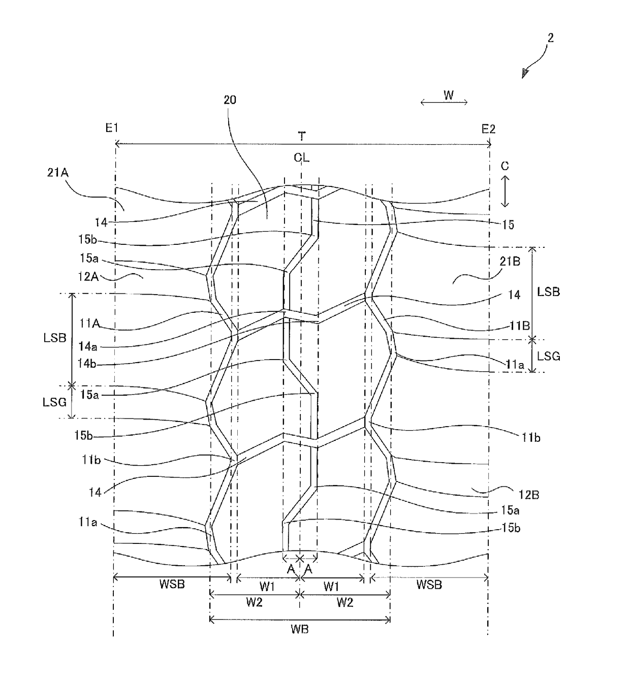
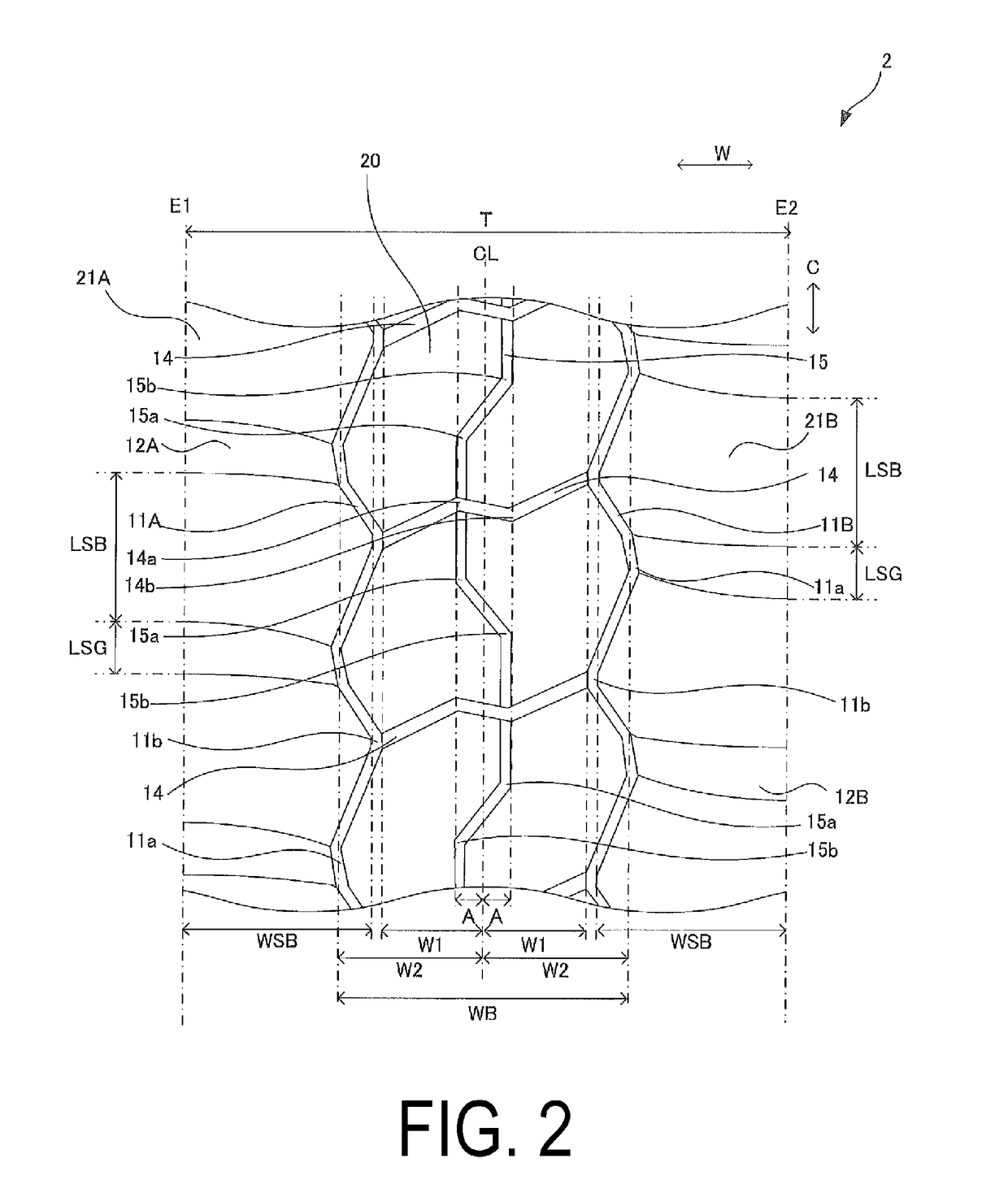
The patent describes a pneumatic tire that can improve heat resistance in the central portion of the tire. This is done by satisfying a certain range of requirements, such as the maximum width of the center blocks and the distance from the secondary groove to the tire equator line. By doing this, the tire can better resist heat build-up, which is a common issue with tires in this region. Overall, the technology improves the tire's ability to handle heat in the center region, making it a more durable and reliable option for drivers.

Problems solved by technology

However, a large tread center region land portion area leads to an increase in the amount of heat build-up, and a small groove area leads to the amount of heat dissipated decreasing.
As a result, heat build-up resistance is reduced.

Method used


Image

  • Pneumatic Tire
  • Pneumatic Tire
  • Pneumatic Tire

Examples


working examples

[0106, Conventional Example, Comparative Examples

[0107]To examine the effects of a tire according to the present embodiment, test tires with varying tread patterns were manufactured and wear resistance performance and heat build-up resistance performance of each were tested. The size of the test tires was 46 / 90R57.

Evaluation of Wear Resistance Performance

[0108]The manufactured test tires were mounted to an actual vehicle (200 ton dump truck) and driven at an average speed of 18 km / h for 4000 hours on an unpaved road surface. Thereafter, the amount of wear was measured. The reciprocal of the results were expressed as index values with the measurement result of the Conventional Example described below being defined as the reference (index value of 100). Larger index values indicate superior wear resistance.

Evaluation of Heat Build-Up Resistance Performance

[0109]Indoor drum testing was performed on the test tires after being mounted to TRA specified rims with a rim size of 29.00-6.0, i...


PUM


Abstract

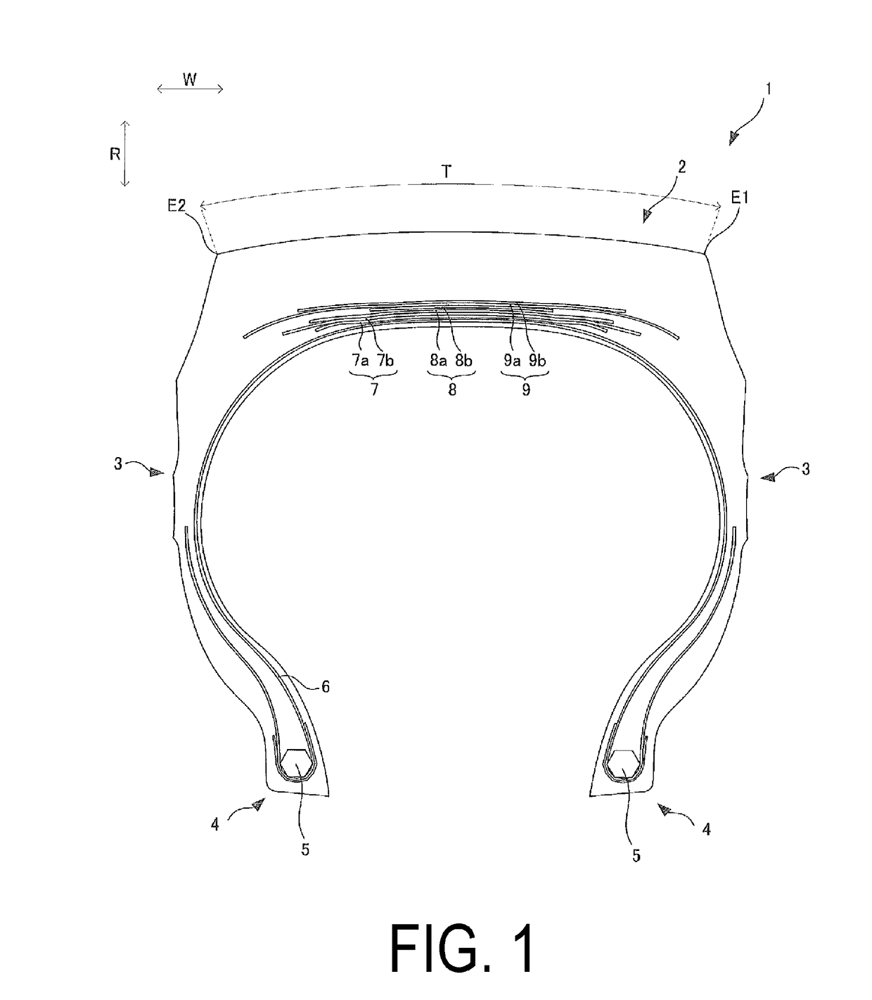
A pneumatic tire includes a plurality of center lug grooves disposed at intervals in a tire circumferential direction that extend crossing a tire equator line and include a first groove turning portion and a second groove turning portion; a plurality of shoulder lug grooves disposed in the intervals between the plurality of center lug grooves in the tire circumferential direction extending outward in the tire width direction, an inner end in the tire width direction being disposed outward of an end of the center lug groove in the tire width direction; a pair of circumferential main grooves to which the ends of the center lug grooves and the inner ends of the plurality of shoulder lug grooves in the tire width direction alternately connect; and a circumferential secondary groove disposed around the entire circumference of the pneumatic tire with a wave-like shape.

Description

TECHNICAL FIELD[0001]The present technology relates to a pneumatic tire with a tread pattern.BACKGROUND ART[0002]There is currently a demand for pneumatic tires to be improved in various performance areas. Such improvement may be realized through the design of tread patterns. Heavy duty tires have been provided with a tread pattern designed with improved traction performance in mind.[0003]For example, a heavy duty pneumatic tire is known which improves both traction characteristics on bad roads until the terminal stage of wear and wet performance at high-speeds in a compatible manner (see Japanese Unexamined Patent Application Publication No. H09-136514A). This heavy duty pneumatic tire includes a tread provided with at least one circumferential main groove extending in the circumferential direction, and a plurality of lateral grooves disposed on opposite sides of the circumferential main groove at intervals in the circumferential direction. The plurality of lateral grooves are conn...

Claims


Application Information

Patent Timeline
Patent Type & Authority Applications(United States)
IPC IPC(8): B60C11/11B60C11/13B60C11/03
CPCB60C11/11B60C11/0304B60C2200/065B60C2011/0353B60C11/13B60C11/0311B60C11/1369B60C2011/0346B60C2011/0355B60C2011/0372B60C11/03
Inventor YAMAGUCHI, YUKIHITOKAKUTA, SHOEIHAMANAKA, HIDEKITAUCHI, RISASATO, TOSHIYUKI
Owner THE YOKOHAMA RUBBER CO LTD
Learn More