Speaker vibrating member and method of making the same

a technology of vibrating member and speaker, which is applied in the direction of diaphragm construction, electromechanical transducer, transducer diaphragm, etc., can solve the problems of poor elastic restoring force, low fatigue resistance, and overly rigid vibration of the vibrating member, so as to improve the sound quality of the speaker and improve the flexibility. , the effect of remarkable fatigue resistan

Active Publication Date: 2017-08-31
OHARA HIROSHI
View PDF0 Cites 6 Cited by
  • Summary
  • Abstract
  • Description
  • Claims
  • Application Information

AI Technical Summary

Benefits of technology

[0009]A primary objective of the present invention is to provide a method for making a speaker vibrating member such that a rubber layer is formed on a resin layer of the fiber cloth. In such a way, the speaker vibrating member produced may have a better flexibility and an exceptional fatigue resistance (i.e. high elastic restoring force), and the sound quality of the speaker may be improved.
[0010]A secondary objective of the present invention is to provide a method for making a speaker vibrating member such that multiple rubber layers are formed on a resin layer of the fiber cloth. Hence, the number of the rubber layers may be adjusted accordingly for a desired stiffness of the fiber cloth, so the speaker vibrating member produced may have an even better flexibility and a more outstanding fatigue resistance. As a result, the speaker manufactured with such speaker vibrating member may provide enhanced sound quality.
[0011]Another objective of the present invention is to provide a method for making a speaker vibrating member such that a release layer is formed on the outermost rubber layer of the fiber cloth. In such a way, the mold-sticking problem may be prevented in the formation step.
[0012]A further objective of the present invention is to provide a speaker vibrating member manufactured with rubber. Such speaker vibrating member is configured to have an exceptional fatigue resistance so as to improve the sound quality of the speaker.
[0027]The present invention is advantageous in that the speaker vibrating member manufactured by the method provided has a higher flexibility and a remarkable fatigue resistance; consequently, the sound quality of the speaker may be enhanced. In particular, after the speaker vibrating member is impregnated with the rubber solution for multiple times, multiple rubber layers may be formed on the resin layer. The effect of the rubber layer is most prominent when SBR is used as the solvent in the rubber solution. As a result, users may adjust the stiffness of the fiber cloth as desire, so the speaker vibrating member is manufactured with a higher flexibility and a more outstanding fatigue resistance for providing a better sound quality. In addition, when the fiber cloth is being impregnated for the last time, it is impregnated with a release agent to form a release layer on the outermost rubber layer. In such a way, the fiber cloth may be prevented from sticking with the mold during the formation step.

Problems solved by technology

However, such speaker vibrating members have the downside of being overly stiff, having low fatigue resistance (i.e. having poor elastic restoring force) and lacking flexibility.
Hence, such speaker vibrating members are easily fatigued and thus may easily rupture, thereby compromising the overall sound effect of the speaker.
Hence, during the demolding process, the speaker vibrating member shaped portion may easily be stuck with the mold.

Method used


Image

  • Speaker vibrating member and method of making the same
  • Speaker vibrating member and method of making the same
  • Speaker vibrating member and method of making the same

Examples


Embodiment Construction

[0035]The accompanying drawings are included to provide a further understanding of the invention, and are incorporated in and constitute a part of this specification.

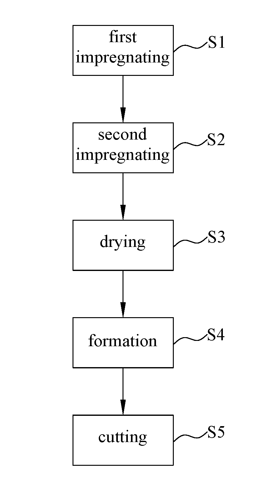
[0036]FIG. 3 is a flow chart showing the steps of a method for making a speaker vibrating member in accordance with the present invention. As shown in FIG. 3, the method for making a speaker vibrating member according to the present invention includes the following steps:

[0037]First impregnating step S1: impregnating a fiber cloth with a resin solution for at least one time. In the present embodiment, the fiber cloth is impregnated with the resin solution for one time only. In other embodiments of the present invention, the fiber cloth may be impregnated with the resin solution for multiple times.

[0038]Second impregnating step S2: removing the fiber cloth from the resin solution, and impregnating the fiber cloth with a water-based rubber solution for at least one time. Preferably, the fiber cloth is impregnated with the...


PUM


Abstract

The present invention provides a method for making a speaker vibrating member, including: impregnating a fiber cloth with a resin solution for at least one time; removing the fiber cloth from the resin solution, and impregnating the fiber cloth with a water-based rubber solution for at least one time; drying the fiber cloth; forming at least one speaker vibrating member shaped portion on a dried fiber cloth; and cutting the at least one speaker vibrating member shaped portion off from the dried fiber cloth to acquire the speaker vibrating member. In such a way, the fiber cloth may be prevented from sticking with the mold during the formation step due to the protection provided by the release layer. In addition, the speaker vibrating member manufactured by the method has a higher flexibility and a remarkable fatigue resistance; consequently, the sound quality of the speaker may be enhanced.

Description

CROSS-REFERENCE TO RELATED APPLICATION[0001]This application claims the priority of Taiwanese patent application No. 105105961, filed on Feb. 26, 2016, which is incorporated herewith by reference.BACKGROUND OF THE INVENTION[0002]1. Field of the Invention[0003]The present invention relates to a speaker vibrating member and a method of making the same.[0004]2. The Prior Arts[0005]FIG. 1 illustrates a structure of a moving-coil speaker 1. When the moving-coil speaker 1 is in operation, electricity is configured to flow through a voice coil 14 to generate an electromagnetic field. The electromagnetic field generated is orthogonal to a magnetic field of a permanent magnet 15 of the moving-coil speaker 1, so the voice coil 14 is applied with a force and is moved correspondingly. In such a way, a drum paper 11 may vibrate in a vertical direction and an up-down direction to cause air vibrations and thereby emitting audio frequency. Therefore, a vibrating member is usually referring to the d...

Claims


Application Information

Patent Timeline
Patent Type & Authority Applications(United States)
IPC IPC(8): H04R7/12H04R31/00
CPCH04R7/125H04R2307/025H04R2307/021H04R31/003H04R9/043H04R9/06H04R2307/029
Inventor OHARA, HIROSHI
Owner OHARA HIROSHI
Why Eureka
Try Eureka