Bipolar X-Ray Module

a bipolar x-ray module and x-ray source technology, applied in the direction of electrical discharge tubes, basic electric elements, electrical equipment, etc., can solve the problems of general limit the voltage of x-ray sources to 70 kv and below

Active Publication Date: 2017-08-31
NEWTON SCI
View PDF2 Cites 21 Cited by
  • Summary
  • Abstract
  • Description
  • Claims
  • Application Information

AI Technical Summary

Benefits of technology

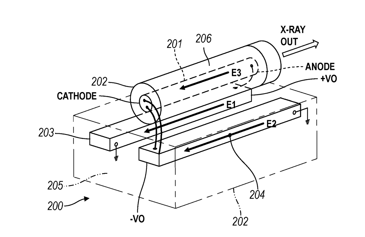
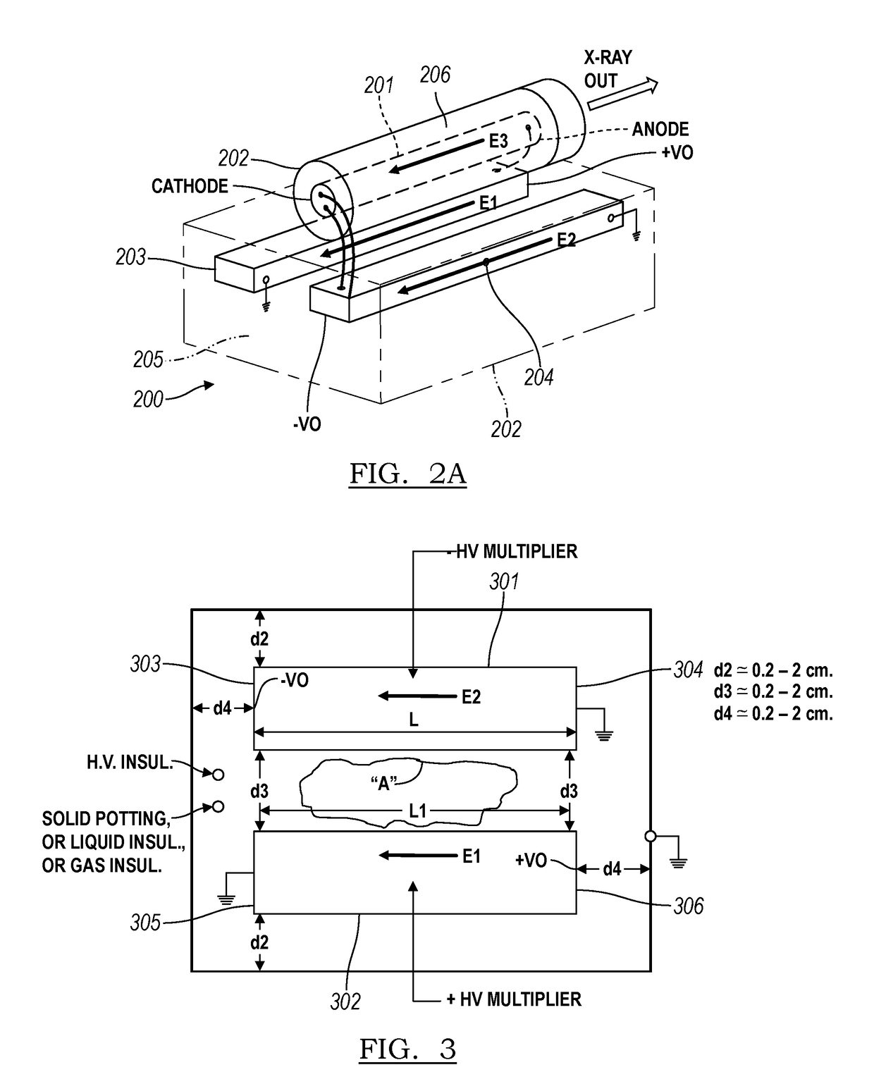
[0004]The present application provides a bipolar x-ray tube module. The bipolar x-ray tube module includes a bipolar x-ray tube and at least two voltage...

Problems solved by technology

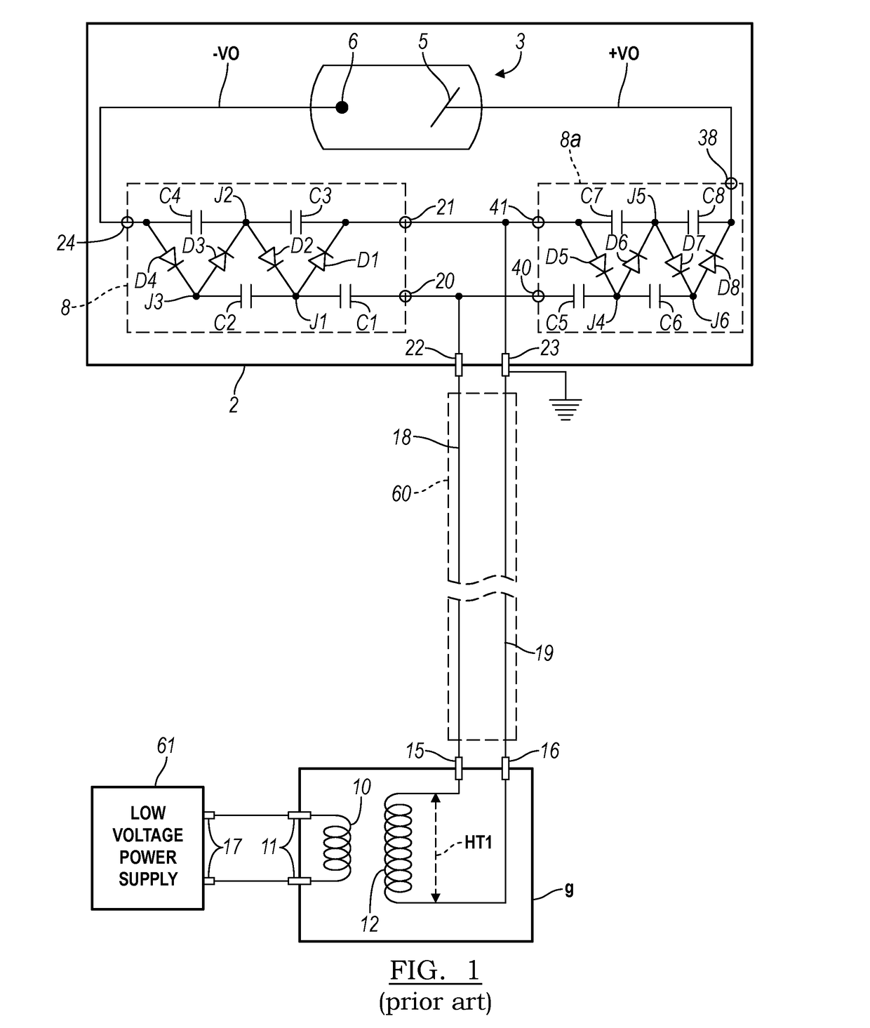
In such conventional systems, however, the voltages of the x-ray sources have been generally limited to 70 kV and below because of the size req...

Method used


Image

  • Bipolar X-Ray Module
  • Bipolar X-Ray Module
  • Bipolar X-Ray Module

Examples


Embodiment Construction

[0014]There are several important applications that require the use of x-ray energies higher than those produced in the current generation of compact x-ray sources suitable for hand-held use. These include the accurate identification and quantification of elements at depths within certain materials, as well as the identification of certain heavy elements (e.g., lead and cadmium), imaging of objects inside sheet metal enclosures (such as car doors or metal lockers), and numerous medical and dental imaging applications. These applications generally require the use of higher voltage sources (e.g., 80 to 200 kV) for x-ray production. Increasing the voltage level of the high voltage, however, generally requires that the length and diameter of the x-ray tube be increased in order to provide sufficient high voltage insulation between the anode and cathode conductors inside the vacuum envelope of the x-ray tube. Increased x-ray tube size therefore, requires an increase in the size of the ha...


PUM


Abstract

The present application provides a bipolar x-ray tube module. The bipolar x-ray tube module may include a bipolar x-ray tube and at least two voltage multipliers. The voltage multipliers may be positioned such that the voltage gradient of the first voltage multiplier is substantially parallel to the second voltage multiplier in order to provide a compact configuration.

Description

RELATED APPLICATIONS[0001]The present patent document claims the benefit of the filing date under 35 U.S.C. §119(e) of Provisional U.S. Patent Application Ser. No. 62 / 300,351, filed Feb. 26, 2016, which is hereby incorporated by reference.TECHNICAL FIELD[0002]The present application relates to systems and methods for providing compact bipolar X-ray sources for use in field portable or hand-held x-ray imaging instruments and analytical instruments, and relates in particular to the design and construction of high voltage x-ray sources for use in field portable or hand-held x-ray instruments.BACKGROUND[0003]Interest in the measurement of material properties using x-ray techniques has resulted in the development of compact, low power consumption x-ray sources for portable x-ray analytical instruments. Examples of such instruments are the hand-held x-ray fluorescence analyzers currently available from companies such Thermo Fisher Portable Analytical Instruments, Bruker and Olympus. There...

Claims


Application Information

Patent Timeline
IPC IPC(8): H05G1/10H01J35/16H05G1/06H01J35/08H01J35/06
CPCH05G1/10H01J35/08H01J2235/087H05G1/06H01J35/16H01J35/06H01J35/186H01J35/116
Inventor KLINKOWSTEIN, ROBERT E.SHEFER, RUTH E.
Owner NEWTON SCI
Why Eureka
Try Eureka