
Audio encoder and decoder using a frequency domain processor with full-band gap filling and a time domain processor

a frequency domain and time domain technology, applied in the field of audio signal encoding and decoding, can solve the problems of reducing audio quality, reducing the accuracy of known frequency domain encoders, and reducing audio quality, so as to reduce the effect of low bitrate perceptual annoyance, efficient downsampling, and reducing the transform siz

Active Publication Date: 2017-09-07
FRAUNHOFER GESELLSCHAFT ZUR FOERDERUNG DER ANGEWANDTEN FORSCHUNG EV
View PDF37 Cites 9 Cited by
  • Summary
  • Abstract
  • Description
  • Claims
  • Application Information

AI Technical Summary

Benefits of technology

This patent describes a method for encoding and decoding audio signals using two different types of processors. One processor uses a time domain encoding method, while the other uses a frequency domain encoding method with a gap filling function. The frequency domain processor is capable of accurately encoding the audio signals up to a certain frequency, while the time domain processor is able to encode the signals with high resolution. The patent also describes a switchable combination of both processors, which allows for seamless switching between the two coding strategies and enables the efficient processing of signals with challenging characteristics. The technical effects of this patent include improved audio bandwidth and better seamless integration of different encoding methods.

Problems solved by technology

In particular when lowest bit rates are to be achieved, the employed coding leads to a reduction of audio quality that often is primarily caused by a limitation at the encoder side of the audio signal bandwidth to be transmitted.
However, specifically for non-speech signals having prominent harmonics in the high frequency band, the known frequency domain encoders have a reduced accuracy and, therefore, a reduced audio quality due to the fact that such prominent harmonics can only be separately parametrically encoded or are eliminated at all in the encoding / decoding process.
This bandwidth extension functionality increases the bitrate efficiency but, on the other hand, introduces further inflexibility due to the fact that both encoding branches, i.e., the frequency domain encoding branch and the time domain encoding branch are band limited due to the bandwidth extension procedure or spectral band replication procedure operating above a certain crossover frequency substantially lower than the maximum frequency included in the input audio signal
However, in USAC, the band-limited core is restricted to transmit a low-pass filtered signal.
However, the so generated spectrum has a lot of spectral gaps.
The high frequency portion, however, can be strongly uncorrelated due to the fact that there might be a different high frequency noise on the left side compared to another high frequency noise or no high frequency noise on the right side.
Thus, when a straightforward gap filling operation would be performed that ignores this situation, then the high frequency portion would be correlated as well, and this might generate serious spatial segregation artifacts in the reconstructed signal.

Method used


Image

  • Audio encoder and decoder using a frequency domain processor with full-band gap filling and a time domain processor
  • Audio encoder and decoder using a frequency domain processor with full-band gap filling and a time domain processor
  • Audio encoder and decoder using a frequency domain processor with full-band gap filling and a time domain processor

Examples


Embodiment Construction

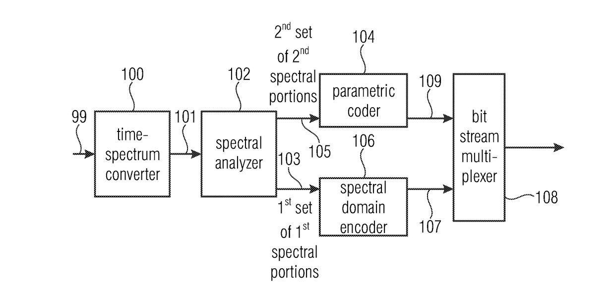
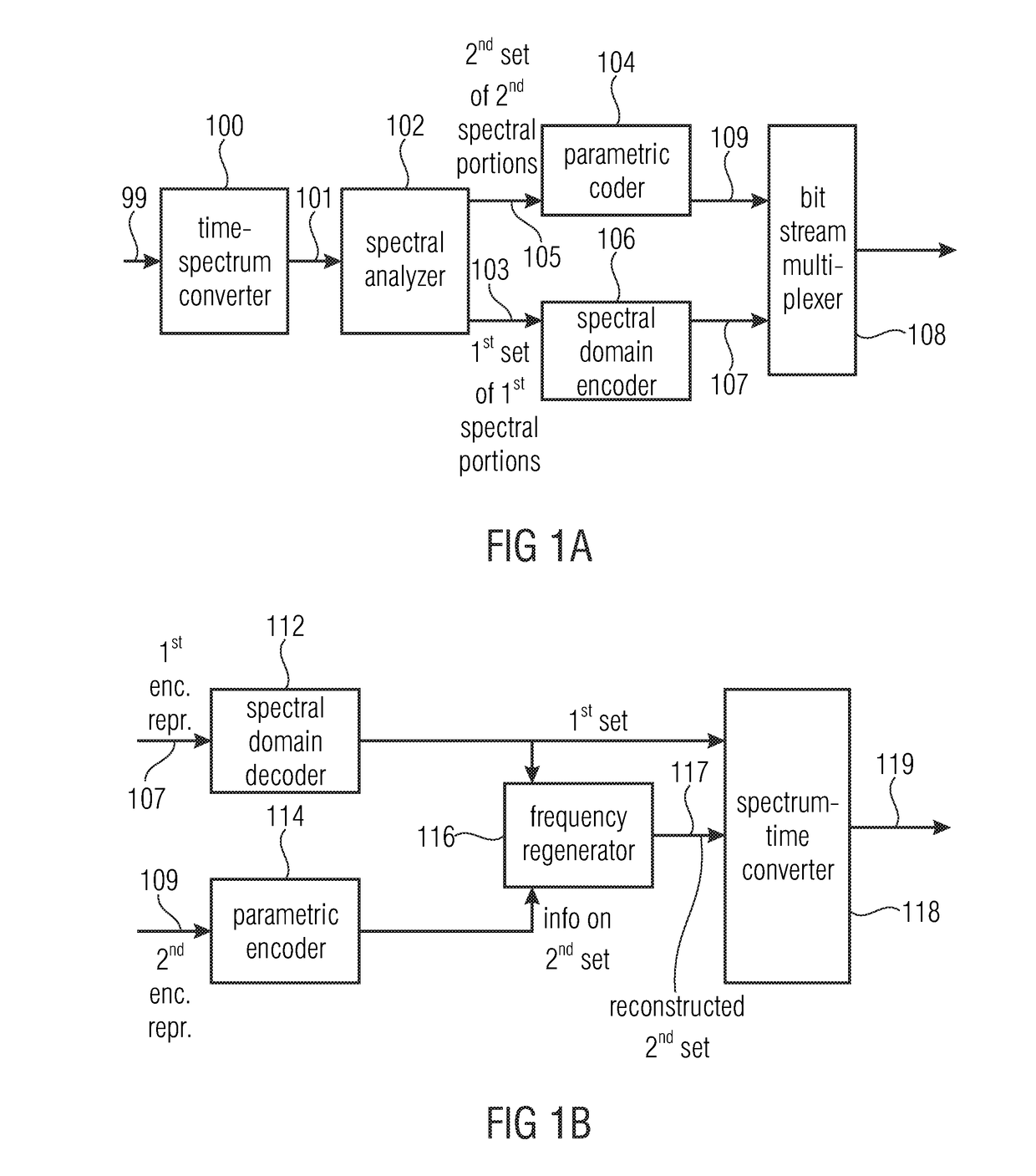
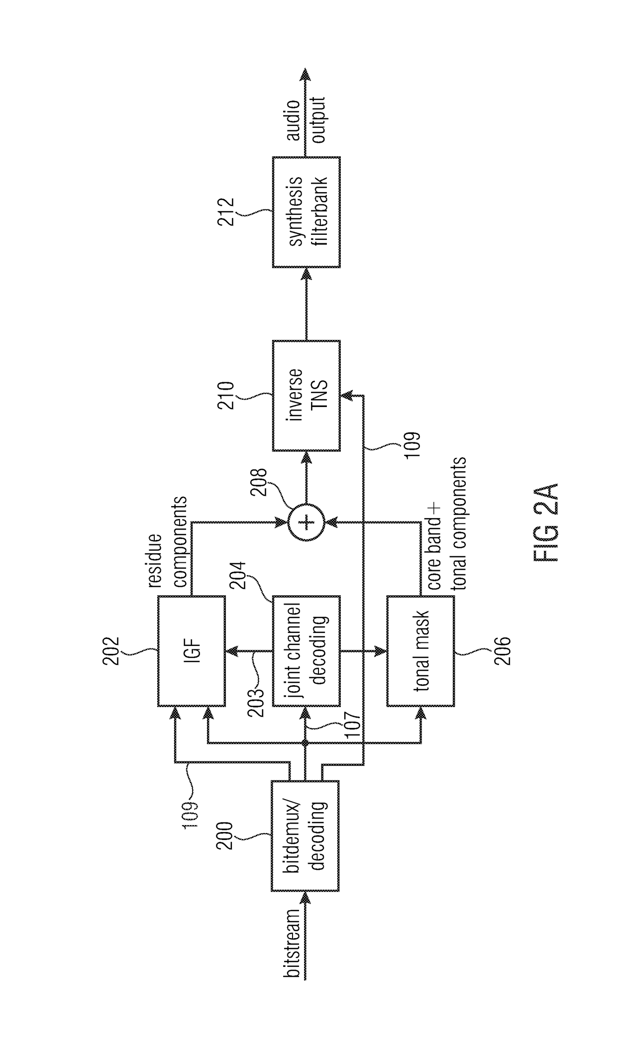
[0079]FIG. 6 illustrates an audio encoder for encoding an audio signal comprising a first encoding processor 600 for encoding a first audio signal portion in a frequency domain. The first encoding processor 600 comprises a time frequency converter 602 for converting the first input audio signal portion into a frequency domain representation having spectral lines up to a maximum frequency of the input signal. Furthermore, the first encoding processor 600 comprises an analyzer 604 for analyzing the frequency domain representation up to the maximum frequency to determine first spectral regions to be encoded with a first spectral representation and to determine second spectral regions to be encoded with a second spectral resolution being lower than the first spectral resolution. In particular, the full-band analyzer 604 determines which frequency lines or spectral values in the time frequency converter spectrum are to be encoded spectral-line wise and which other spectral portions are t...


PUM


Abstract

An audio encoder for encoding an audio signal has: a first encoding processor for encoding a first audio signal portion in a frequency domain, having: a time frequency converter for converting the first audio signal portion into a frequency domain representation; an analyzer for analyzing the frequency domain representation to determine first spectral portions to be encoded with a first spectral resolution and second regions to be encoded with a second resolution; and a spectral encoder for encoding the first spectral portions with the first spectral resolution and encoding the second portions with the second resolution; a second encoding processor for encoding a second different audio signal portion in the time domain; a controller for analyzing and determining, which portion of the audio signal is the first audio signal portion encoded in the frequency domain and which portion is the second audio signal portion encoded in the time domain; and an encoded signal former for forming an encoded audio signal having a first encoded signal portion for the first audio signal portion and a second encoded signal portion for the second portion.

Description

CROSS-REFERENCE TO RELATED APPLICATIONS[0001]This application is a continuation of co-pending International Application No. PCT / EP2015 / 067003, filed Jul. 24, 2015, which is incorporated herein by reference in its entirety, and additionally claims priority from European Application No. 14178817.4, filed Jul. 28, 2014, which is also incorporated herein by reference in its entirety.BACKGROUND OF THE INVENTION[0002]The present invention relates to audio signal encoding and decoding and, in particular, to audio signal processing using parallel frequency domain and time domain encoder / decoder processors.[0003]The perceptual coding of audio signals for the purpose of data reduction for efficient storage or transmission of these signals is a widely used practice. In particular when lowest bit rates are to be achieved, the employed coding leads to a reduction of audio quality that often is primarily caused by a limitation at the encoder side of the audio signal bandwidth to be transmitted. H...

Claims


Application Information

Patent Timeline
Patent Type & Authority Applications(United States)
IPC IPC(8): G10L19/18G10L19/028G10L19/032G10L19/06G10L19/26
CPCG10L19/18G10L19/06G10L19/028G10L19/032G10L19/265G10L19/04G10L19/02G10L21/038G10L19/24G10L19/20
Inventor DISCH, SASCHADIETZ, MARTINMULTRUS, MARKUSFUCHS, GUILLAUMERAVELLI, EMMANUELNEUSINGER, MATTHIASSCHNELL, MARKUSSCHUBERT, BENJAMINGRILL, BERNHARD
Owner FRAUNHOFER GESELLSCHAFT ZUR FOERDERUNG DER ANGEWANDTEN FORSCHUNG EV
Learn More